Checking drilling ranges and cavities for proper marking
This procedure belongs to step 3 of the simple nesting workflow.
- Position your objects horizontally and vertically in the top view.
- Rotate your objects about the Z-axis in the top view.
- Check if all cavities and drillings are correct.
- Specify the drilling range for objects with unrecognized drillings.
- Mark the cavities for objects with unrecognized cavities.
- Set bars for all objects.
This procedure belongs to step 6 of the complete nesting workflow.
- Delete any incorrect machined areas.
- Change the status of objects and delete non-required objects.
- Position your objects horizontally and vertically in the top view.
- Rotate your objects about the Z-axis in the top view.
- Adjust the height position of your objects and/or rotate them about the X/Y-axis (required for multilayered blanks).
- Check if all cavities and drillings are correct.
- Specify the drilling range for objects with unrecognized drillings.
- Mark the cavities for objects with unrecognized cavities.
- Create a sinter bar for objects that require a sinter bar.
- Set drops for objects that require drops.
- Mark the attachment for objects with an attachment.
- Activate anterior tooth editing for the desired object)
- Edit or delete labels milled on objects.
- Set bars for all objects.
If you activated the automatic detection of cavities or drill holes in the STL import view, you need to check for all objects if dentalcam has correctly recognized drill holes and cavities.
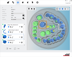
- Open the Nesting view for adjusting objects with the following icon in the main icon bar:

Checking drilling ranges
Drilling ranges can either be unmarked or incorrectly marked. You need to thoroughly check both ends of every drill hole in your blank for both cases.
Recommendation: For a better overview, hide elements in the blank display. Showing/hiding elements of the blank display
How to check drilling ranges
- Switch to the bottom view. Toggling the view of the blank display
-
Zoom in on an object with at least 1 drill hole.
Set the view onto the drill hole.
- Check whether the following applies:
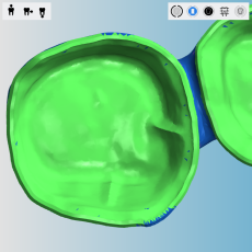
- The opening surface of the drill hole is completely marked in green. The opening surface also includes connection geometries and inner edges.
- The opening surface is even and doesn’t have any sharp bends
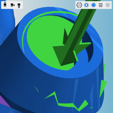
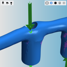
- An arrow indicates the correct drilling direction (pointing perpendicularly “into” the drill hole).
- Arrow pointing perpendicularly into the drill hole
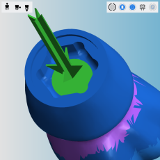
- Even opening surface marked in green
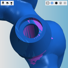
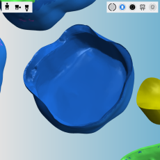
- Hexagonal connection geometry of an abutment without marking
- Correctly marked drilling range of the hexagonal connection geometry
- Repeat step 3 for the second end of the drill hole.
- If a drill hole hasn’t been recognized correctly, correct it manually via the editing function for specifying the drilling range
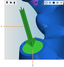
A correctly recognized drilling range
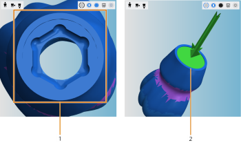
A correct drilling range for a hexagonal connection geometry
Examples of incorrectly marked drilling ranges
Checking cavities
Cavities can either be unmarked or incorrectly marked. You need to thoroughly check every cavity in your blank for both cases.
How to check cavities
-
Switch to the bottom view. Toggling the view of the blank display
-
Zoom in on an object with a cavity.
-
Make sure that all cavities including the preparation line areas are marked green.
Other areas must not be marked green.
-
If a cavity hasn’t been recognized correctly, mark it manually via the editing function for marking cavities
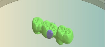
Examples of incorrectly marked cavities
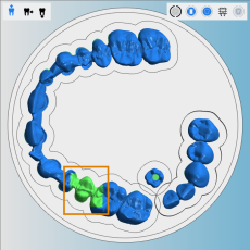
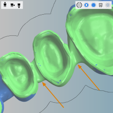
In the following example, dentalcam fused 3 cavities into 1 incorrect cavity. You can see this in the enlarged view from below: The interdental space is wrongly marked green (indicated by the arrows):
What's next?
If drilling ranges or cavities need correcting:
Marking and deleting drilling ranges
All editing functions for objects:
Editing functions in the nesting view
If you are finished with adjusting objects:
If you are unsure whether you are finished nesting the current blank, see the simple and complete nesting workflow:
