Marking and deleting drilling ranges
This procedure belongs to step 4 of the simple nesting workflow.
- Position your objects horizontally and vertically in the top view.
- Rotate your objects about the Z-axis in the top view.
- Check if all cavities and drillings are correct.
- Specify the drilling range for objects with unrecognized drillings.
- Mark the cavities for objects with unrecognized cavities.
- Set bars for all objects.
This procedure belongs to step 7 of the complete nesting workflow.
- Delete any incorrect machined areas.
- Change the status of objects and delete non-required objects.
- Position your objects horizontally and vertically in the top view.
- Rotate your objects about the Z-axis in the top view.
- Adjust the height position of your objects and/or rotate them about the X/Y-axis (required for multilayered blanks).
- Check if all cavities and drillings are correct.
- Specify the drilling range for objects with unrecognized drillings.
- Mark the cavities for objects with unrecognized cavities.
- Create a sinter bar for objects that require a sinter bar.
- Set drops for objects that require drops.
- Mark the attachment for objects with an attachment.
- Activate anterior tooth editing for the desired object)
- Edit or delete labels milled on objects.
- Set bars for all objects.
Drilling ranges must be marked for optimum editing. Optimum editing includes grinding repetitions and using optional tools.
Incorrectly marked and unmarked drilling ranges must be marked manually with the editing function for drilling ranges.
-
Angled drillings must always be marked manually.
-
For instructions on how to check for unmarked or incorrectly marked drilling ranges, see Checking drilling ranges and cavities for proper marking.
-
Before you can correct markings of drilling ranges, you need to delete the incorrect marking.
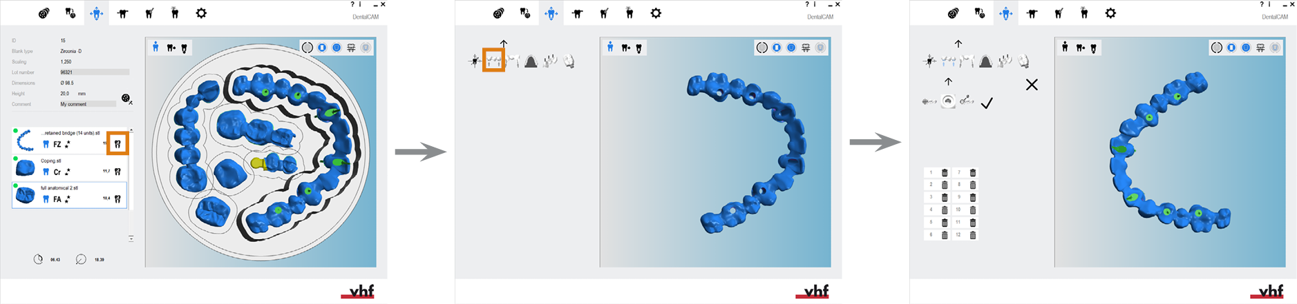
- Open the Nesting view for adjusting objects with the following icon in the main icon bar:

Deleting and marking drilling ranges in the nesting view for adjusting objects
Watch the video

YouTube video – When viewing this video, personal data is sent to YouTube, LLC, USA. Privacy statement
Deleting drilling ranges
-
(Optional) Select the desired object in the blank display.
-
dentalcam highlights the object in the object list with a colored border.
-
Open the editing functions for the required object with the following icon in the left column:

-
The icon bar for the editing functions is displayed.
-
Open the editing function for marking drilling ranges with the following icon:

- dentalcam displays a list with all marked drilling ranges in the left column.
- To find the desired drilling range in the list, select the corresponding arrow which indicates the drilling direction in the blank display.
- dentalcam marks the selected drilling range in the list with a blue border.
- To delete the drilling range, select the following icon:

- dentalcam removes the entry from the list and the visual representation of the drilling range in the blank display.
- Manually mark the drilling range.
-
Save your changes with the lower arrow icon:

-
Close the area for the editing function with the upper arrow icon:
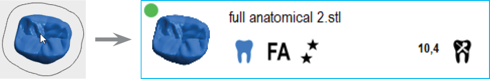
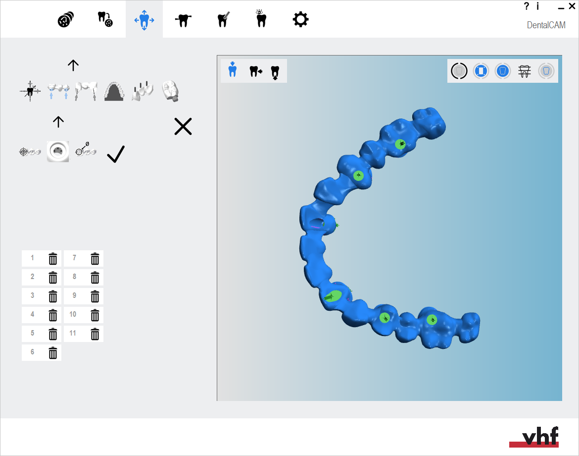
Figure is an example
Opening the editing function for marking drilling ranges (icons marked orange)
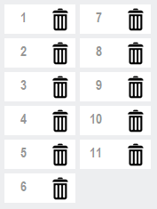
A list of all marked drilling ranges for 1 object
Selecting the arrow of a drilling range to mark the corresponding list entry
Marking drilling ranges
-
(Optional) Select the desired object in the blank display.
-
dentalcam highlights the object in the object list with a colored border.
-
Open the editing functions for the required object with the following icon in the left column:
-
The icon bar for the editing functions is displayed.
-
Open the editing function for marking drilling ranges with the following icon:
- The icon bar for marking drilling ranges is displayed in the left column.
-
If the object has any incorrectly marked drilling ranges, delete them.
-
Start the workflow by selecting the following icon in the left column:

-
Position the view so that you look into the drill hole from the drilling direction. You must be able to see a good portion of the wall of the drill hole.
-
Continue by selecting the following icon in the left column:

-
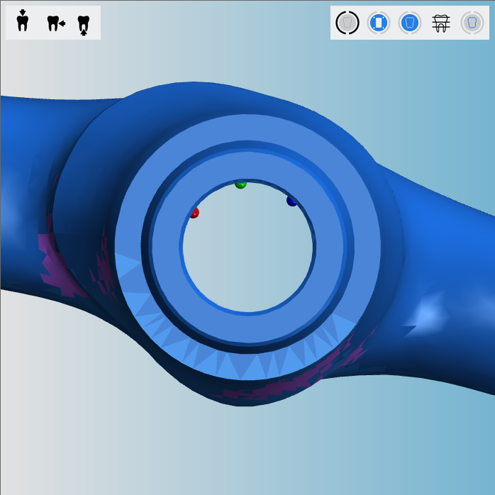
Select 3 measuring points on the wall of the drill hole by clicking on the drill hole wall.
-
The points must be perpendicular to the drilling direction.
-
Distribute the measuring points slightly without moving the view.
-
Do not position the measuring points on a connection geometry or torsion protection.
-
dentalcam may re-position your measuring points. As long as all points still lie on the wall, everything’s fine.
-
- As soon as you have set the 3rd measuring point, dentalcam switches to the top view so that you can check the position of the measuring points.
-
Continue by selecting the following icon in the left column:

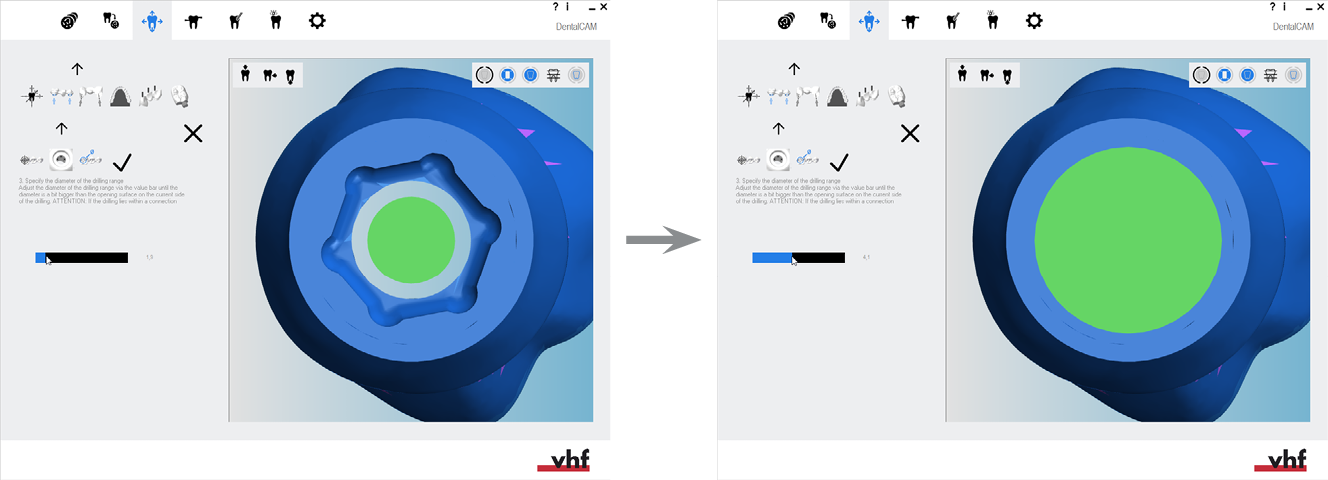
- dentalcam displays a value bar for the diameter of the drilling range in the left column.
-
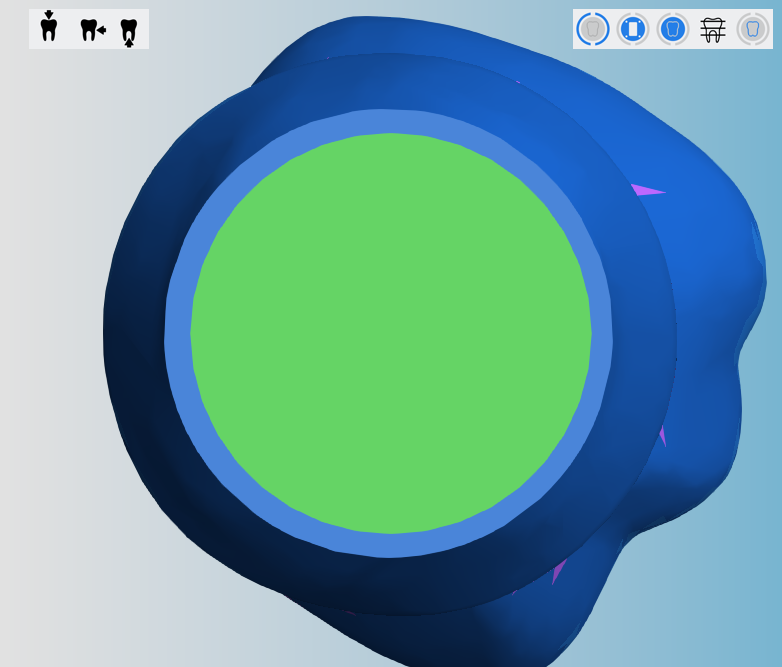
Set the diameter of the drilling range. Increase and decrease the diameter of the drilling range with the value bar.
-
The drilling range must be slightly larger than the opening surface of the drill hole.
-
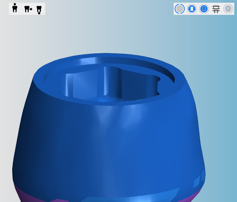
Connection geometries and inner edges are part of the opening surface and must also be marked completely.
-
-
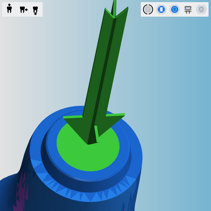
Finish the workflow by selecting the following icon in the left column:

- dentalcam draws the drilling direction as a green arrow and the drilling range as a green surface.
-
Make sure that the entire opening surface of the drill hole is marked as the drilling range. However, the result is not always as optimal as in the example above because STL files have a finite precision.
However, if the opening surface is not marked completely or the opening surface is curved, delete the drilling range and mark it again.
-
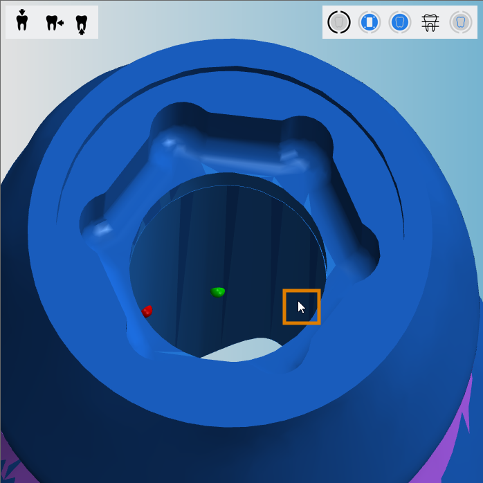
Mark the opposite end of the drill hole.
Figure is an example
![]()
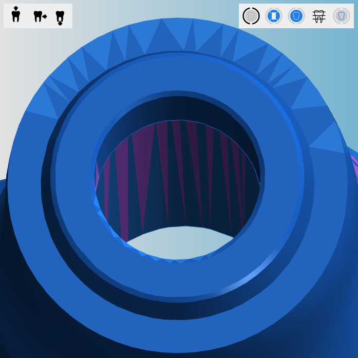
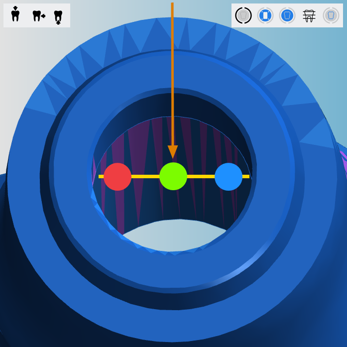
Diagram: Setting measuring points; drilling direction indicated by the arrow
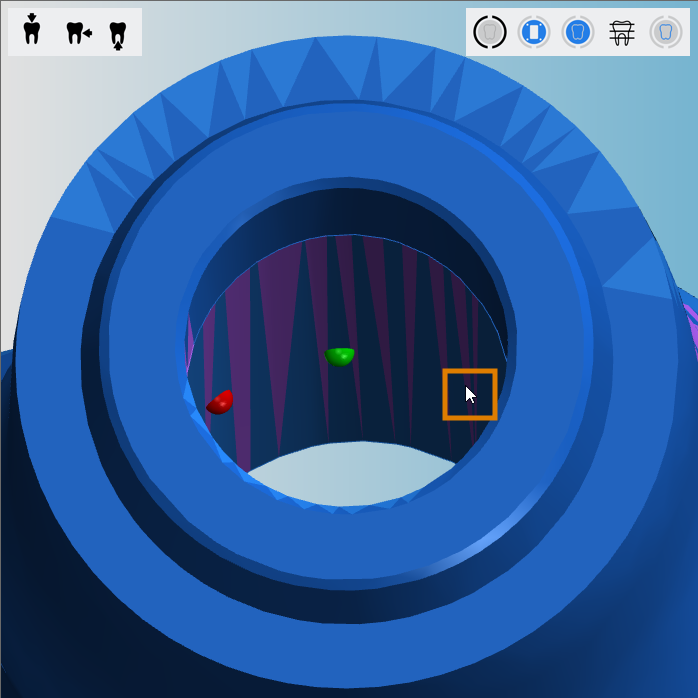
The orange marking indicates the position of the third measuring point
Example: Abutment with connection geometry
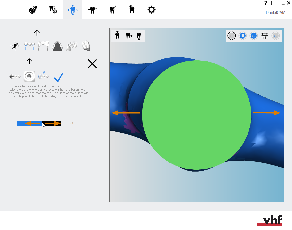
Specifying the drilling range
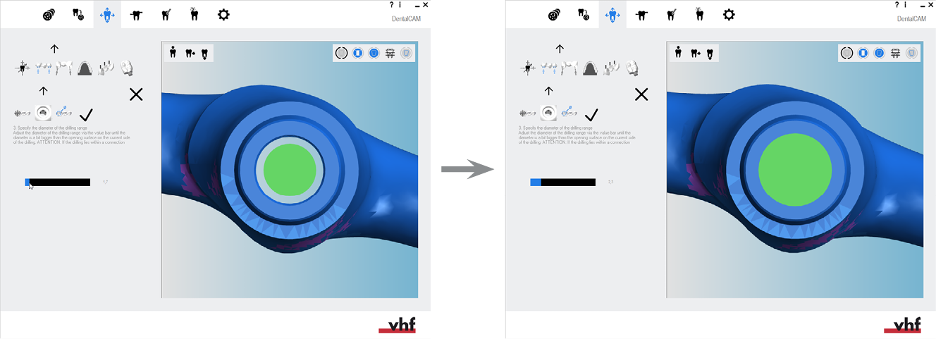
Correct diameter for a standard drill hole
Example for defining the diameter of an abutment with the connection geometry and inner edge:
What's next?
Next editing function for objects:
If you are finished with adjusting objects:
If you are unsure whether you are finished nesting the current blank, see the simple and complete nesting workflow: