Machine overview
Watch the video
YouTube video – When viewing this video, personal data is sent to YouTube, LLC, USA. Privacy statement
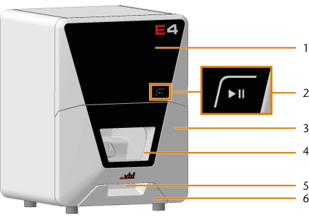
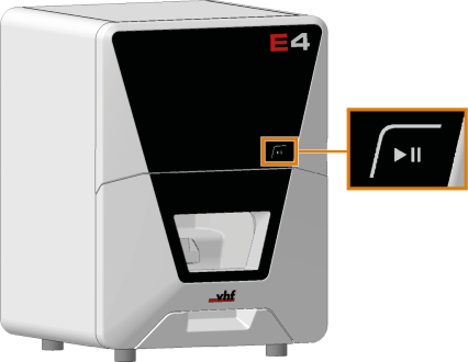
Front side of the machine
-
Service cover for access to the machine interior
-
Start button
-
Working chamber door
-
View window to the working chamber
-
Recessed grip for opening the working chamber door
-
Cooling liquid tank or dry machining tank
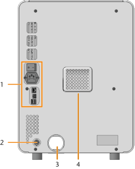
Rear side of the machine
-
Connection panel
-
Air extraction interface (6 pins, IEC 61076-2-106)
-
Hose connection for the air extraction system
-
Openings for the ventilation of the working chamber
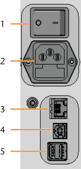
Connection panel
-
Main power switch
-
Power connection including glass fuse T6,3A L250V
-
Network port (Ethernet RJ-45)
-
1 x USB port 2.0 Type B (for future extensions)
-
2 x USB port 2.0 Type A (for future extensions)
Start button
The Start button is used to start and interrupt a job.
-
To activate the Start button, place a finger on it.
Do not press the button.
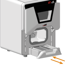
Working chamber door
The working chamber door locks the working chamber and protects the user from injuries during operation.
You cannot open the door when the machine is switched off or while the axes are moving.
- To open or close the working chamber door, pull it upwards or push it downwards with your hand. Use the recessed grip of the door.
Lever for emergency release of the working chamber door
The lever for the emergency release is located on the right underside of the machine.
Emergency opening of the working chamber door
Working chamber
You can insert blanks and tools into the working chamber. This is where the blanks are machined.
-
Spindle with collet chuck for picking up tools
-
Measuring sensor
-
Insert for the AirTool
-
Tool magazine insert
-
Tool magazine
-
Blank holder
-
Drain insert for wet machining
Colors of the working chamber lighting
|
Color |
Status |
Working chamber door |
|---|---|---|
|
Green |
The machine is ready for operation. |
unlocked |
|
White |
The machine is ready for operation. |
unlocked |
|
Blue |
|
locked |
|
Red |
A machine malfunction has occured. |
locked |
Cooling liquid tank and dry machining tank
Your E4 uses the following interchangeable tanks:
-
Cooling liquid tank for wet machining
-
Dry machining tank for dry machining (extra equipment
 Physical component which must be obtained separately and which adds new functionality to your machine.)
Extra equipment![]() Physical component which must be obtained separately and which adds new functionality to your machine. can be obtained from your customer service provider.
Physical component which must be obtained separately and which adds new functionality to your machine. can be obtained from your customer service provider.
Depending on the machining mode, the required tank must be located in the compartment below the working chamber.
Without a dry machining tank in place, a connected air extraction system does not generate the required negative pressure in the working chamber.
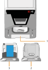
-
Compartment for the cooling liquid tank / dry machining tank
-
Dry machining tank
-
Cooling liquid tank
Switching from dry to wet machining
Exchanging the cooling liquid and cleaning the cooling liquid tank
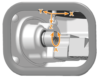
Axes
This machine has
-
Linear axes X, Y, Z
The spindle moves along these axes.
-
Rotational axis A
The blank holder rotates about this axis.
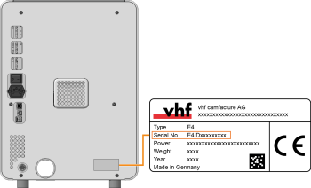
Identification plate and serial number
The identification plate of the machine contains identifying information such as the serial number. You can find the identification plate and machine serial number at the following location:
