Watch the video
YouTube video – When viewing this video, personal data is sent to YouTube, LLC, USA. Privacy statement
-
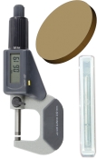
Have ready:
-
Close dentalcnc.
-
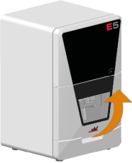
Open the working chamber door.
-
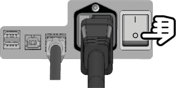
Switch off the machine at the main power switch.
-
CAUTION!Wear gloves.
-
NOTICE! Remove all tools from the tool magazine and remove the AirTool from the insert E1.
-
Disconnect the A-axis cable of the A-B axis module from the cable socket:
-
Carefully cut the cable tie at the cut line (marked green) with the side cutter. Do not damage the A-axis cable in the process.
-
Pull the A-axis cable downwards out of the cable socket.
-
Remove the cable tie.
NOTICE! Damage to the A-axis cable if you apply the side cutter too deeply.
-
-
Disconnect the A-axis cable of the A-B axis module:
-
Open the knurled nut at the left on the underside of the A-B axis module.
-
Pull the cable off downwards at the plug.
-
-
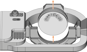
Remove the blank from the blank holder if present.
-
Pull the 4 cover caps (marked orange) off the 4 fixing screws on the A-B axis module.
-
Unscrew the 4 fixing screws of the A-B axis module with the angle screwdriver. Remove the fixing screws and washers.
-
Grasp the A-B axis module with both hands and pull it forwards off the driveshaft. Remove the A-B axis module from the working chamber.
-
Remove the blank holder from the removed A-B axis module. Attach the blank holder to the spare A-B axis module.
Please use the following instructions: Exchanging the blank holder.
-
Using both hands, slide the spare A-B axis module onto the driveshaft.
-
Insert the positioning pin on the A-B axis module (4) into the opening in the driveshaft (2).
-
Insert the positioning pin on the driveshaft (1) into the opening in the A-B axis module (3).
-
-
Positioning pin on the driveshaft
-
Opening in the driveshaft
-
Opening in the A-B axis module
-
Positioning pin on the A-B axis module
-
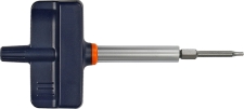
Use the torque screwdriver (5.0 Nm with TX25 bit). Tighten the A-B axis module crosswise with the 4 washers (marked orange) and the 4 fixing screws.
-
Attach the 4 cover caps to the 4 fixing screws of the A-B axis module.
-
Connect the A-axis cable to the connector at the left side of the underside of the A-B axis module:
-
Plug in the connector of the cable.
-
Screw the connector tight with the knurled nut.
-
-
Fasten the A-axis cable to the cable socket (marked green) with the cable tie:
-
Insert the cable tie into the cable socket from below. Bend it around the brackets of the cable base.
-
Press the A-axis cable into the cable base and hold it in this position.
-
Insert the end of the cable tie without the eyelet into the eyelet on the cable tie. Tighten the cable tie.
-
Cut off the protruding part of the cable tie with the side cutter.
-
-
Close the working chamber door.
-
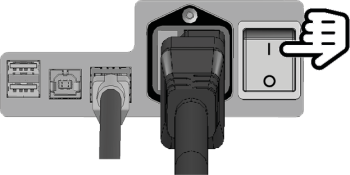
Switch on the machine at the main power switch.
-
Start dentalcnc.
-
Calibrate the machine with manual tool change:
-
In the Machine data view in dentalcnc, turn on the manual tool change for the T17 position.
-
Assign the calibration tool to the AirTool insert E1 in the tool management view.
-
Calibrate the machine with dentalcnc. When prompted, manually insert the calibration tool into the collet chuck.
-
Measure the measuring sensor with dentalcnc.
-
Drill tool positions into the tool magazine inserts.
Drilling tool positions (holes) into new tool magazine inserts
-
Calibrate the machine with automatic tool change:
-
In the Machine data view in dentalcnc, turn on the manual tool change for the T17 position.
-
Insert the calibration tool into AirTool insert E1.
-
Calibrate the machine with dentalcnc.
-
Use a test specimen to check the mechanical accuracy of the machine.
-
If the test specimen is out of tolerance, contact Customer Service.
- Open the Maintenance section with the following icon in the main toolbar:

-
 Select the icon shown for the Exchange tool magazine inserts entry.
