Editing machining parameters and optional tools
While machining is controlled with dentalcnc, there are some machining parameters that are important for job calculation. Therefore, you can find these in the application settings in dentalcam.
They affect the machining quality and speed.
- Open the dentalcamapplication settings window with the following icon in the main icon bar:

- Open the view for machining parameters with the following icon in the program settings icon bar:

General and blank type specific parameters
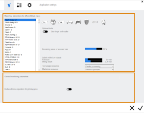
The machining parameters view consists of 2 sections:
- In the upper area of the machining parameters view, you can specify parameters that are specific to individual blank types.
- In the bottom area, you can specify general machining parameters.
Editing general machining parameters
The general machining parameters apply to all jobs.
-
If you want to reduce machining noise during grinding jobs, activate the Reduced noise operation for grinding jobs option.
If activated, it reduces the feed rate as well as the tool path distance for grinding jobs. This increases the machining time.
If your machine cannot grind objects, this setting has no effect.
- dentalcam takes the new setting into account for all future calculated jobs.
Editing machining parameters for individual blank types and activating optional tools
Some machining parameters need to be specified separately for each blank type. These include:
- Optional tools for high quality machining
- Values for oversize of fits
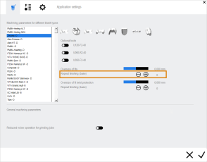
- Residual areas of bars (when bars get reduced)
- Manual check of cavities
As these parameters are important for the job calculation, you need to specify them in dentalcam (not in dentalcnc).
- Open the dentalcamapplication settings window with the following icon in the main icon bar:

- Open the view for machining parameters with the following icon in the program settings icon bar:

-
From the selection list, select the blank type that you want to specify the machining parameters for.
The available blank types depend on the currently selected machine and the blank types which are activated in the application settings.
- From the icon bar to the right of the selection list, select the machining parameter group that you want to edit.
- General parameters
- Occlusal surfaces
- Basal surfaces
- Cavities (general)
- Cavities in inlays /onlays
- Cavities in veneers
- Drill holes
- Attachments
-
The machining parameters for the selected combination of parameter group and blank type display in the central area of the window.
- Change the settings as required. You can find a description of the parameters below.
- Save your changes by selecting the following icon:

The settings for cavities are divided into settings for cavities in inlays / onlays, veneers and all other indications.
The icon bar for selecting the machining parameter group
Optional tools
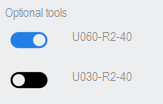
In this area, you can activate or deactivate tools for optional finishing steps. These additional finishing steps can increase the machining quality significantly, but they also increase the machining time. The optional tools are designated with their match codes.
| Icon |
Area of application |
Match code | Function | ||||||||||
|---|---|---|---|---|---|---|---|---|---|---|---|---|---|
|
|
General parameters |
|
|
||||||||||
|
|
Occlusal surfaces |
|
|
||||||||||
|
|
Basal surfaces |
x060-Rx-xx |
For finishing fine details in interdental areas of bridges |
||||||||||
|
|
Cavities |
x060-Rx-xx |
For working out narrow areas in cavities, which may occur in anterior crowns, for example |
||||||||||
|
|
Cavities of inlays / onlays |
x060-Rx-xx |
For working out narrow areas inside the cavities of inlays / onlays |
||||||||||
|
|
Cavities on veneers |
x060-Rx-xx |
For working out narrow areas inside the cavities of veneers |
||||||||||
|
|
Drill holes |
|
|||||||||||
|
|
Attachments |
|
|||||||||||
|
|
Anterior tooth machining |
|
|||||||||||
General parameters
Some blank types can either be machined wet or dry. If you use a machine that is capable of wet and dry machining, you can toggle the machining mode for these blank types as follows:
- Select the blank type from the blank type list in the left column.
- Open the general parameters by selecting the following icon:

- One of the following icon displays next to the Wet machining label:
- Blank type will be machined wet:

- Blank type will be machined dry:

- To change the machining mode for all future jobs which use this blank type, select the icon.
- The icon changes color and you have toggled the operating mode.
If the icon doesn’t display, you cannot toggle the machining mode for the selected blank type or machine.
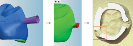
Bars are partially reduced to make it easier to detach objects from the blank at predetermined breaking points.
Partially reduced bars also reduce manual rework.
Use the Remaining area of reduced bars value bar in the machining parameters to define the remaining size of partially reduced bars.
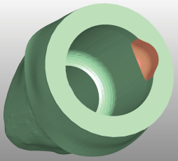
From left to right: A partially reduced bar in the nesting view, in the residual material display and on the machined object (marked orange)
Do you want to know more about the different types of bars? Types of bars
- Use the Remaining area of reduced bars value bar to specify how much material will be left after the reduction.

The value bar Remaining area of reduced bars
Example: If you select 30%, the bars will be reduced until their size is 30% of their original size.
With this setting you can specify how thick in mm the wall of bars will be for prefabricated abutments.

- Use the value bar to specify the bar wall thickness.
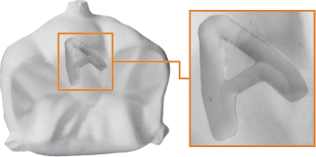
In the Labels milled on objects area you specify settings for labels which are milled on objects.
- You can add labels to objects during import via the calculation option. Specify the calculation options.
- You can edit the label text during nesting.
- Via the Font size value bar, specify the character height in millimeters.
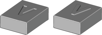
- Via the Milling depth value bar, specify the height or depth of the label:
- Negative values specify the depth of labels. The machine mills the text into the surface of the objects (“recessed label”).
- Positive values indicate the height of the labels: The machine mills the object so that the label sits on top of the surface ("embossed label").
The milling depth determines the type of manual work that you have to perform after machining. Recessed labels have to be filled, embossed labels have to be sanded down.
An important part of calculating jobs is to determine the tool usage for the individual machining steps. This information also determines when tools will be changed, i.e., the tool usage sequence. You can influence this sequence by selecting one of the following entries from the Tool usage sequence drop-down list:
-
Parallel processing The tool usage sequence is determined on the basis of the tools:
The machine fetches a tool and machines all objects in the blank that the tool is required for. Only when the tool is no longer needed for any object, will the machine fetch the next tool. This process is repeated until all objects are fully machined with all required tools.
-
Individual processing The tool usage sequence is determined on the basis of the objects:
The machine processes every object completely with all tools that are required for the object before moving on to the next object. This process is repeated until all objects are fully machined (recommended).
If you use reduced bars in a job, note that they will be reduced after all objects that they are connected with have been fully machined.
- If you activate Parallel processing, bars can only be reduced at the end of the job because that’s the point when all objects are fully machined.
- If you activate Individual processing, bars will be reduced as soon as the individual objects are fully machined.
| Tool usage sequence | Advantages | Disadvantages |
|---|---|---|
|
Parallel processing |
Slightly reduces machining time as tools do not have to be changed so often |
If a tool breaks, the machine may continue to machine with the broken tool for a long period of time. Objects will not be completed until after the last tool has been used |
|
Individual processing |
If a tool breaks, the machine will recognize this during the next tool change. The first objects will be completed relatively soon |
Slightly longer machining time as tools will be changed more frequently |
- Specify the machining sequence of objects within one blank by selecting it from the Machining sequence drop down list.
-
DirectMill optimized dentalcam determines the best order for DirectMill-based machining to make sure that you can start machining immediately after starting the calculation.
If you want to profit from the DirectMill feature and save as much time as possible, select this entry.
- From left to right The machine starts with the leftmost object and finishes with the rightmost object.
- From smallest to largest object The machine starts with the smallest object and finishes with the largest.
-
According to the import list The machine machines objects according to the import list from top to bottom. The import list is part of the STL import view.
Cavities
With the value bar, you can specify the diameter of fits in millimeters. The lower the value, the less material is removed and the narrower the fit will become. The higher the value, the more material is removed and the wider the fit will become.
The oversize of fits often needs to be adjusted to the material because individual materials react differently to the physical forces exerted by the tool. With this parameter, you widen or narrow the individual fits to ensure that their machining is optimal for the material used. Adjusting the oversize of fits in dentalcam also means that you do not have to do this in your CAD application.
-
To adjust the oversize of fits of cavities, use the Oversize of fits value bar in the Cavities section.
For some objects, cavities must be extra precise. For example, when manufacturing telescope crowns, the secondary crown must fit perfectly onto the primary crown. For optimal results 'out-of-the-machine' without additional manual work, dentalcnc can interrupt machining so that you can check the cavities. If they are not precise enough, the machine can rework them multiple times in steps of 2 micrometers until you are satisfied with the result.
This function requires you to be present during machining and operate the CAM computer, because otherwise machining will not continue. Therefore, we recommend activating this function only if you manufacture objects with cavities which require extra high precision.
- To use this feature, activate the Manually check cavities during machining option for the desired blank type.
With this setting you can specify how many times the finishing process of cavities in secondary crowns will be repeated during machining. A higher number will results in a higher precision, but also in more machining time.
Drill holes
You can use a designated tool for finishing cavities in secondary crowns:
- M200-R4-32-C (used with 4-axis machines) or
- M200-R4-35-C (used with 5-axis machines)
The tool names M200-R4-3x-C and M200-R4-3x denote the same physical tool. The 2 versions exist so that dentalcnc can differentiate between the usages.
Using a designated tool for this machining step allows for better tool life values and can increase the finishing quality.
You can activate the tools as follows:
- Select CoCr in the blank type list.
- From the icon bar, select the icon for cavities.
- Activate the Use designated finishing tool for secondary crowns option.
- In dentalcnc, add the M200-R4-32-C or M200-R4-35-C tool to the virtual tool magazine.
- Add the physical tool to the corresponding tool magazine position in your machine.
With the value bar, you can specify the diameter of fits in millimeters. The lower the value, the less material is removed and the narrower the fit will become. The higher the value, the more material is removed and the wider the fit will become.
The oversize of fits often needs to be adjusted to the material because individual materials react differently to the physical forces exerted by the tool. With this parameter, you widen or narrow the individual fits to ensure that their machining is optimal for the material used. Adjusting the oversize of fits in dentalcam also means that you do not have to do this in your CAD application.
-
To adjust the oversize of fits of drill holes, use the Oversize of fits value bar in the Drillings section.
When manufacturing implant-borne objects such as abutments, the drill hole that the titan pin is inserted into (the base) must be machined with high precision for a perfect fit. To achieve this, you can specify how many times the finishing process of these drill holes will be repeated during machining. A higher number will results in a higher precision, but also in more machining time.
With the Oversize of fits rotation protection value bar, you can specify the diameter of twist protections of abutments in millimeters. The lower the value, the less material is removed and the narrower the twist protection will become. The higher the value, the more material is removed and the wider the twist protection will become.
-
Activate the x060-Rx-xx tool in the Optional tools section. The exact tool match code depends on the material that you selected in the left column.
If you don’t activate this tool, this setting will have no effect.

Example: Optional x060-Rx-xx tool for generic Zirconia discs (marked orange)
-
To adjust the oversize of fits of twist protection, use the Oversize of fits rotation protection value bar in the Drillings section.
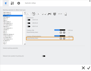
When manufacturing abutments, the twist protection must be machined with high precision for a perfect fit. To achieve this, you can specify how many times the finishing process will be repeated during machining. A higher number will results in a higher precision, but also in more machining time.
-
Activate the x060-Rx-xx tool in the Optional tools section. The exact tool match code depends on the material that you selected in the left column.
If you don’t activate this tool, this setting will have no effect.

Example: Optional x060-Rx-xx tool for generic Zirconia discs (marked orange)
-
Use the
 icon to increase the number of finishing processes or the
  icon to decrease the number.
Attachments
With the Oversize of fits attachments value bar, you can specify the diameter of fits of attachments in millimeters. The lower the value, the less material is removed and the narrower the fit will become. The higher the value, the more material is removed and the wider the fit will become.
-
To adjust the oversize of fits of attachments, use the Oversize of fits value bar in the Drillings section.

