Connecting the machine
Watch the video
YouTube video – When viewing this video, personal data is sent to YouTube, LLC, USA. Privacy statement
The installation steps up to operation are:
Machine installation (schema)
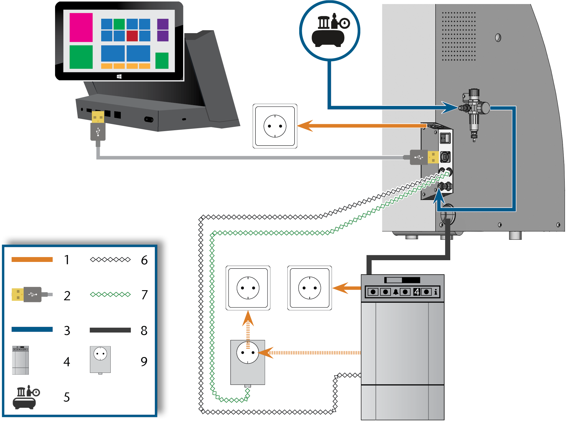
- Power connection
- Pneumatic hose
- Suction unit
- External compressed air supply
- Data cable of supported suction units (optional)
- Control cable of the switching unit (optional)
- Suction hose
- Switching unit (optional)
You can either use the switching unit including the control cable or the data cable of supported suction units. The data cable must be provided by the manufacturer of the suction unit.
How to install the vhf wet grinding module is described in the operating instructions for the module.
The operating instructions are delivered with the vhf wet grinding module. They are also available for download here.
Establishing the electric connection
Short-circuit hazard when the machine is too cold
If the machine is transported from a cold environment into a warmer environment, a short circuit may occur caused by condensate.
- Before switching on the machine after transportation, ensure the following:
- The ambient air has the allowed temperature.
- The machine has the same temperature as the ambient air. This will take at least 48 hours.
- The machine is completely dry.
The machine requires an uninterruptible power supply for proper operation.
- Plug the provided power cable into the power connection at the connection panel of the machine.
-
NOTICE! To avoid job interruptions, install an uninterruptible power supply (UPS), type online / VFI (IEC 62040-3, Class 1) if there are regular power failures or frequent mains voltage fluctuations.
- Insert the plug of the cable into a socket that is protected by a Residual Current Device / Ground Fault Circuit Interrupter.
Installing the pneumatics
You can find specific values and additional requirements in the chapter on technical data. Technical data
The machine requires the compressed air for the following tasks:
- For the opening and closing of the collet chuck during tool changes.
- For the spindle sealing air which prevents foreign bodies from entering the spindle.
- For the sealing air in the working chamber that keeps machining debris away from sensitive machine parts.
- For the ionizer.
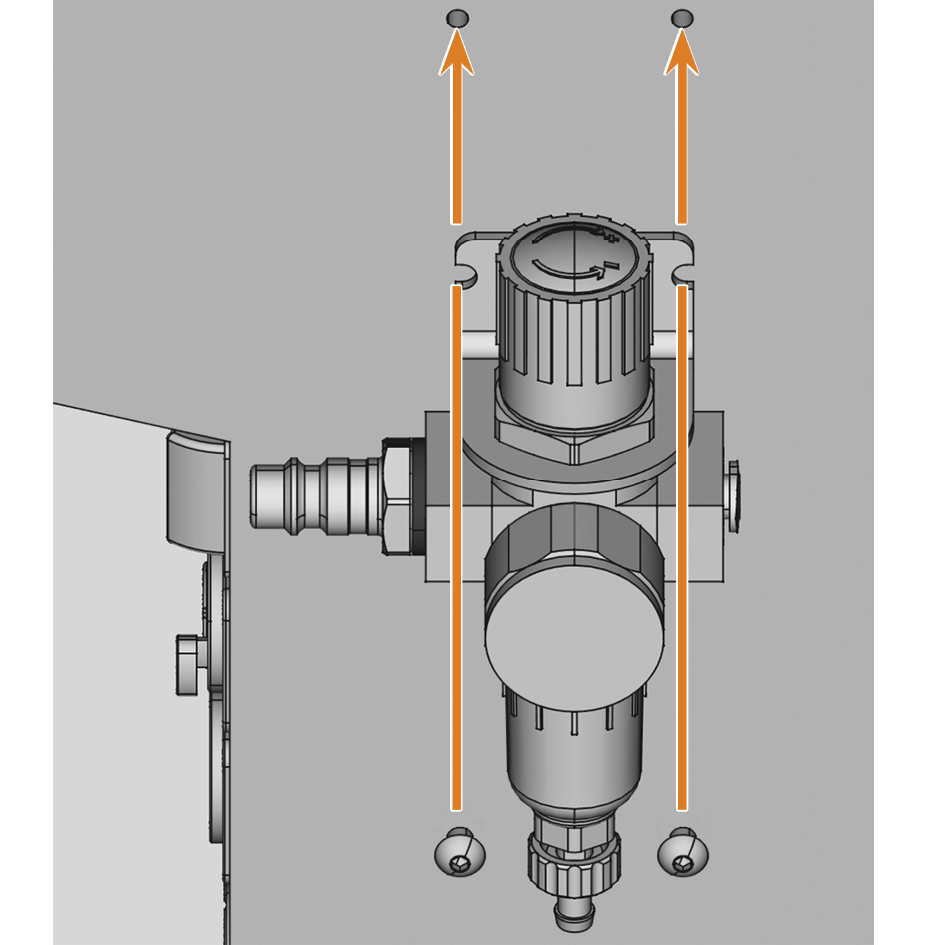
Overview compressed air regulator
The machine is connected to the external air supply via a compressed air regulator. You can use this regulator to monitor and regulate the pressure of the incoming air.
- 1/8” internal thread, fitted with male compressed air connector to connect the external compressed air supply
- 6 mm push-in fitting to connect the machine.
Failure of the water separator caused by a wrong alignment of the compressed air regulator
The compressed air regulator must always be mounted in an upright position because otherwise the water separator will not work.
- Mount the compressed air regulator in an upright position.
On the left side of the machine are 2 drill holes that you can use to mount the compressed air regulator on the machine.
- Mount the compressed air regulator in an upright position, using the oval-head screws provided in the drill holes.
Installing the pneumatic hose
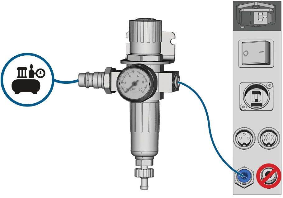
NOTICE! The blue compressed air socket must not be confused with the stainless steel socket for cooling liquid. Otherwise the machine will not work properly.
- Close the main external compressed air supply valve.
- Use the provided pneumatic hose to connect the right pneumatic connection of the compressed air regulator to the pneumatic connection of the machine.
- Connect the external compressed air supply to the left pneumatic connection of the compressed air regulator.
- Thoroughly verify that all external pneumatic hoses are properly seated in their corresponding connections and that the hoses and connectors are undamaged.
- If all hoses and connectors are properly installed and undamaged, open the external compressed air supply valve.
Adjusting the air pressure with the compressed air regulator
Setting the air pressure is only necessary if the air pressure shown by the pressure gauge does not lie between the minimum and maximum air pressure. You can find specific values and additional requirements in the chapter on technical data.
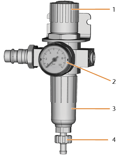
- Rotary knob for pressure regulation
- Pressure gauge for monitoring the outgoing air pressure
- Bowl of the water separator
- Discharge screw
-
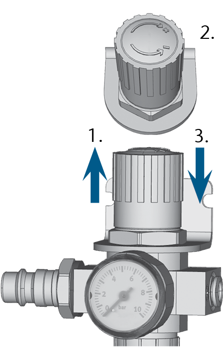
Pull the rotary knob on top of the compressed air regulator slightly upwards.
- Turn the rotary knob in the desired direction:
- Turn it in the “+” direction to increase the pressure
- Turn it in the “-” direction to decrease the pressure
- Push the rotary knob down again.
- The knob is locked and cannot be changed inadvertently.
Installing the air extraction system
Components of the air extraction system:
| Component | Source | Required? | Prerequisite |
|---|---|---|---|
|
Suction unit incl. suction hose |
Customer service, specialist dealers |
Yes |
– |
|
Switching unit |
Customer service* |
No |
Data cable not used |
|
Data cable of supported suction units |
Manufacturer of the suction unit |
No |
Supported suction unit; switching unit not used |
|
Hose connection |
Customer service |
If the suction hose does not fit |
– |
*The switching unit is not available worldwide.
Requirements for the suction unit
You can find specific values and additional requirements in the chapter on technical data. Technical data
- Use a suction device with the following properties only:
- Designed for the commercial use in the dental sector
- Equipped with a filter of the filter class M
- Equipped with safety devices which protect you from static discharges (e. g. through an anti-static suction hose)
Installing the suction unit
You can install the suction unit as follows:
-
Read the documentation for the suction unit. Follow the operating and safety instructions at any time.
-
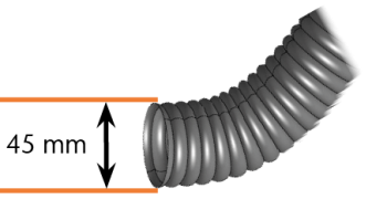
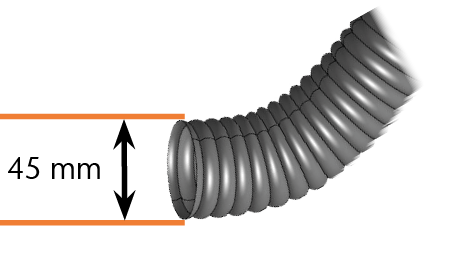
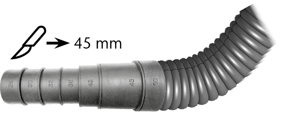
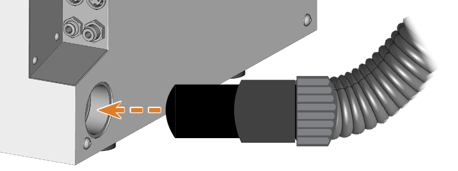
Check if the connection of the suction hose has an outer diameter of 45 mm.
-
If the diameter is different, adjust either the hose or the hose adapter supplied with the suction unit.
Alternative: Use the optional hose connection of vhf.
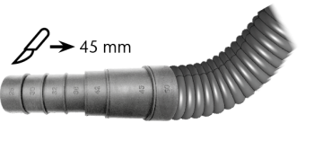
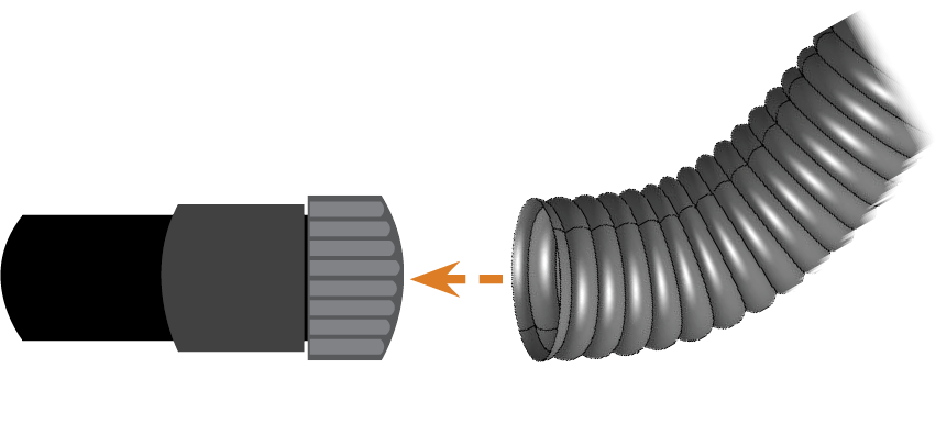
Example: Suction hose with hose adapter
or
Hose connection
-
Insert the suction hose into the opening for the suction unit on the machine. Make sure that the suction hose is properly seated.
-
If you want the machine to automatically switch the suction unit on and off, choose 1 of the following options:
-
Install the switching unit (extra equipment
 Physical component which must be obtained separately and which adds new functionality to your machine.). The switching unit is not available worldwide.
 -
Connect a data cable provided by the suction unit manufacturer to the machine’s air extraction interface.
-
-
Continue with the installation of the suction unit as described in the documentation of the unit.
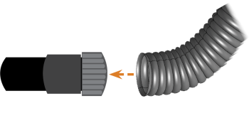
Connecting the suction hose with the optional hose connection
If you cannot connect the suction hose of the suction unit directly to the machine, install the hose connection as follows:
- Turn the thread of the hose connection counterclockwise until the connection is completely open.
- Insert the suction hose of the suction device completely into the hose connection on the side of the thread.
- Turn the thread of the hose connection clockwise as far as you can.
- Insert the hose connection into the opening for the air extraction system of the machine. Ensure it is firmly connected.
If the thread gets detached from the hose connection, place it onto the connection again and turn it clockwise once so that it is screwed to the connection again.
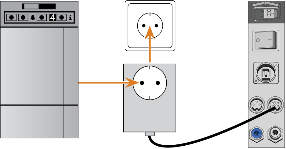
Installing the switching unit
If you want the machine to automatically switch the suction unit on and off, but a data cable is not available, you can use the optional switching unit. The switching unit is not available worldwide.
- Connect the power cable of the suction unit to the switching unit.
- Connect the control cable of the switching unit to the suction device data port at the connection panel of the machine.
- Plug the switching unit into a power socket.