Installing the machine
In which order do I have to install the components of the K5+?
Checking the scope of delivery
- Unpack the machine and ensure that you have received the following items:
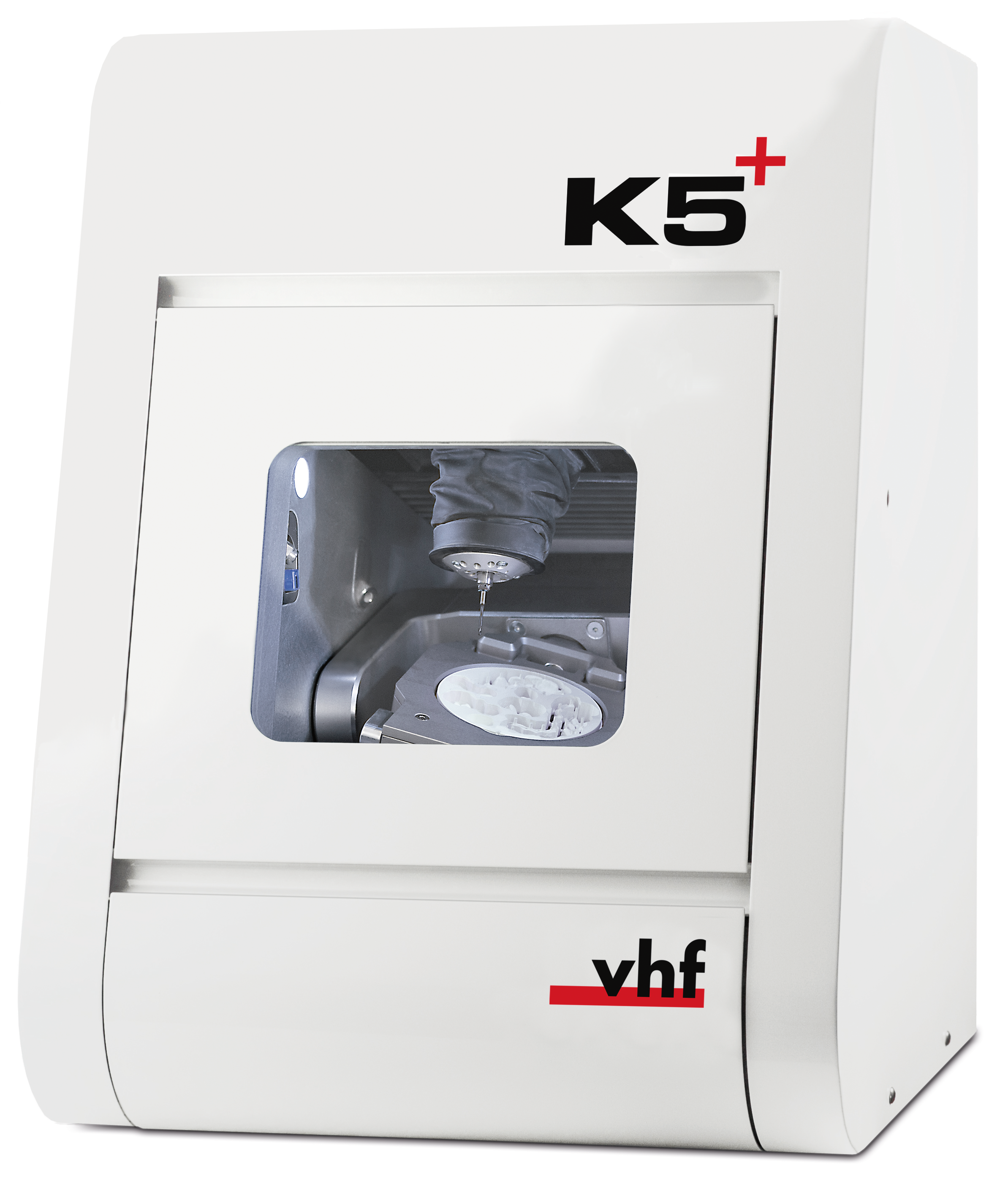
- 1 x Machine K5+
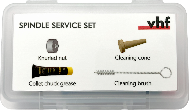
- 1 x Spindle service set
- 1 x Power cable
- 1 x Ethernet network cable (type: straight)
- 1 x Key for the emergency release of the working chamber door
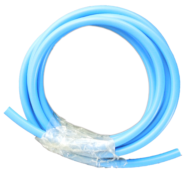
- 1 x Pneumatic hose
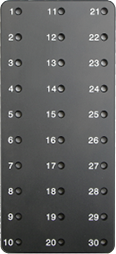
- 1 x Administrated tool board (ATB) in the accessories container
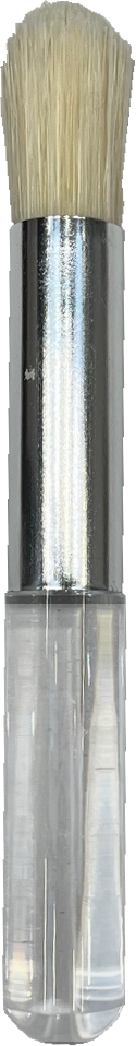
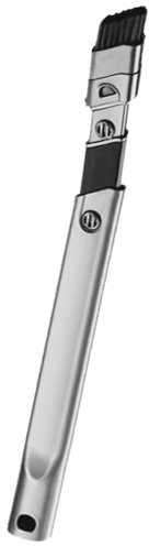
- 1 x Small cleaning brush for the blank holder in the accessories container
- 1 x Crevice nozzle (for cleaning the working chamber)
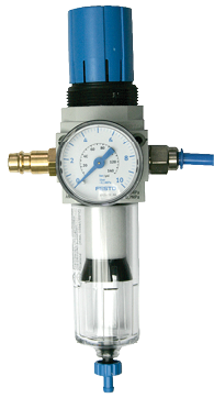
- 1 x Compressed air regulator
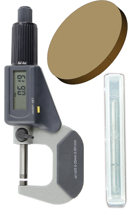
- 1 x Calibration set: 1 micrometer, 3 blanks for manufacturing test and calibration specimens, 1 radius cutter with 2 teeth (P200-R2-40)
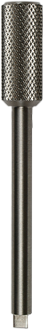
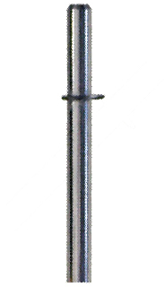
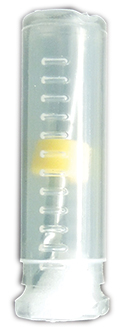
- 1 x Measuring pin
- 2 x Tool magazine inserts
- 1 x Drill bit (2.8 mm) for tool positions
Not shown:
- 1 x Brief machine information
- 1 x Carrying aid for transporting the machine
- 1 x Transport lock in the working chamber
- 1 x Supplement about removing the transport lock
- 1 x Supplement about removing the carrying aid and transport lock
- 2 x Accessory kit in the working chamber
- 4 x Spare screw for the tool magazine cover
-
Transport lock
-
1 x Transport box
-
1 x Top and bottom cushion
-
1 x Transport protection cover
-
1 x Housing protection cover
-
-
Packing set
-
1 x Transport box
-
1 x Top and bottom cushion
-
1 x Transport protection cover
-
1 x Housing protection cover
-
- Keep the packaging of the machine, the carrying aid and the transport lock for future transports.
The installation site must meet the following criteria:
- Firm and even surface, must be able to carry the weight of the machine.
- Alternating current source.
- An operational Residual Current Device / Ground Fault Circuit Interrupter on the electric circuit of the machine.
- Machine requires an external air extraction system.
- Machine requires an external compressed air supply.
- Access to the internet and local computer network via cable.
You can find specific values and additional requirements in the chapter on technical data. Technical data
Damaging of the machine if safety distances are not maintained
If you do not maintain the safety distances, the movable parts of the housing can collide with obstacles when being opened and get damaged. If the ventilation openings are covered, the machine may overheat and get severely damaged.
- Ensure that the following safety intervals are always maintained.
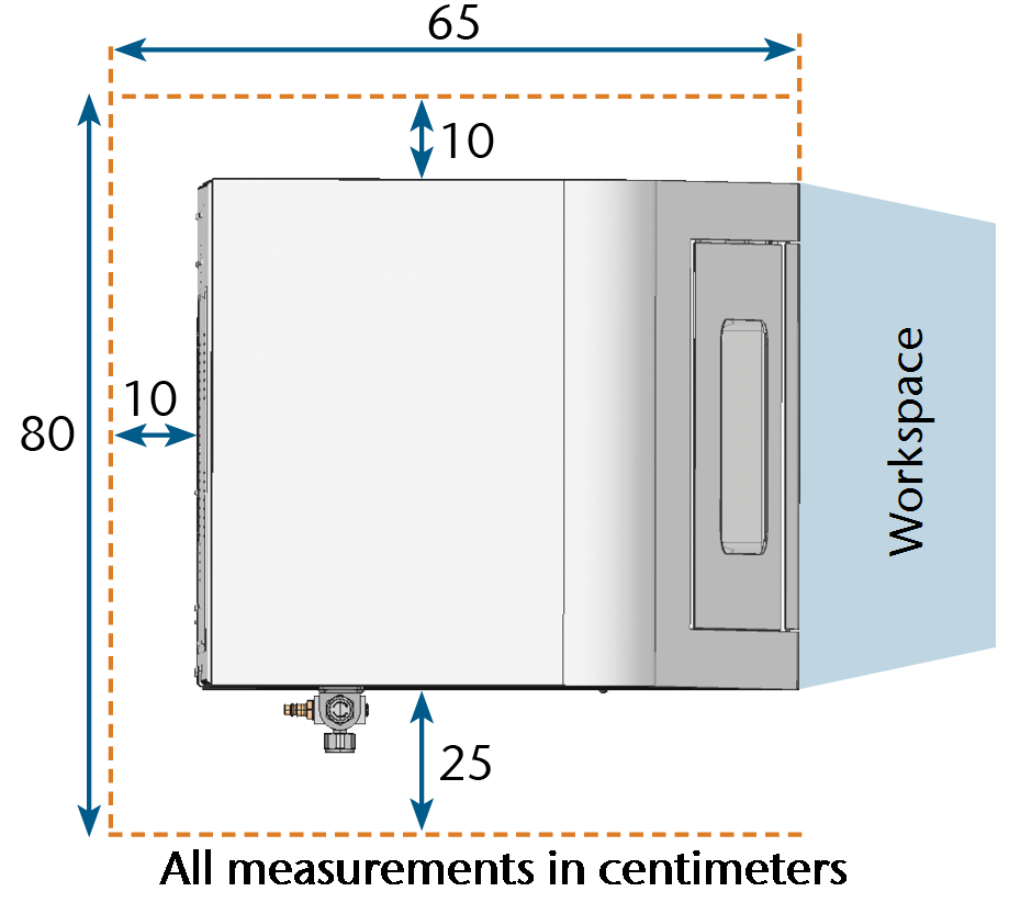
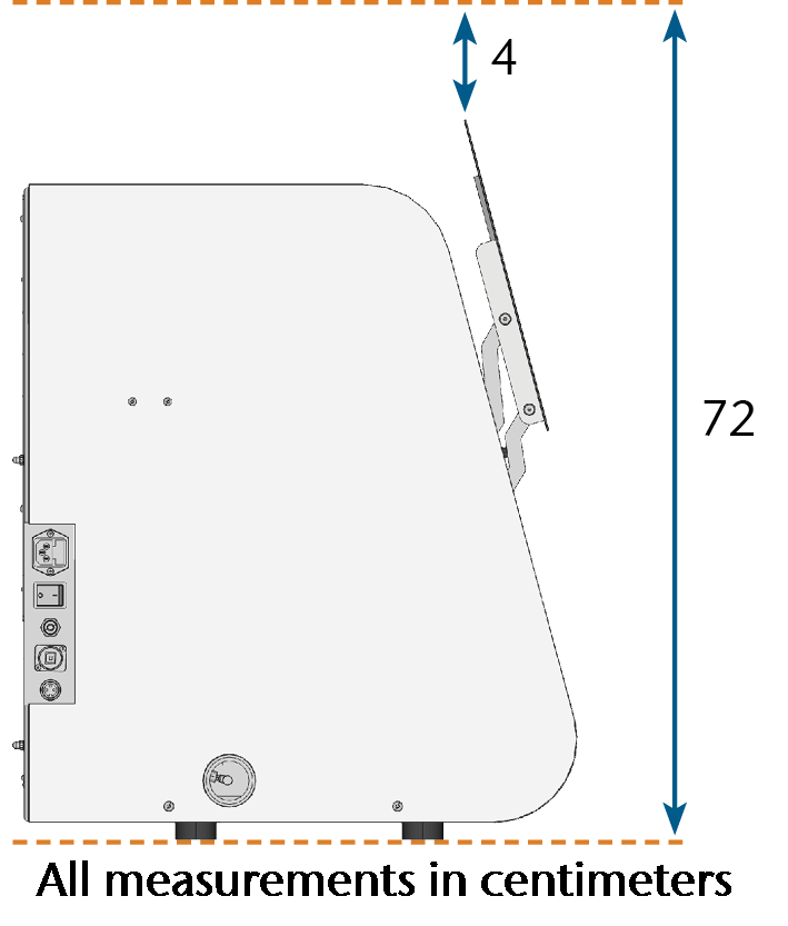
Distances to maintain
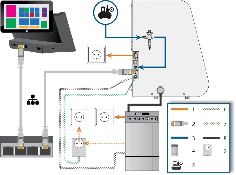
Machine installation (schema)
- Power connection
- Ethernet network cable
- Pneumatic hose
- Suction unit
- External compressed air supply
- Data cable of supported suction units (optional)
- Control cable of the switching unit (optional)
- Suction hose
- Switching unit (optional)
You can either use the switching unit including the control cable or the data cable of supported suction units. The data cable must be provided by the manufacturer of the suction unit.
Damaging of the machine through heavy voltage fluctuations and power surges
Large mains voltage fluctuations and power surges disrupt the control unit and can cause system failures.
- Connect the machine to a separately protected circuit or ensure that no devices are connected that cause severe mains voltage fluctuations when powered on.
- If strong voltage fluctuations cannot be avoided, install a surge protector to safeguard the machine against strong voltage fluctuations.
Short-circuit hazard when the machine is too cold
If the machine is transported from a cold environment into a warmer environment, a short circuit may occur caused by condensate.
- Before switching on the machine after transportation, ensure the following:
- The ambient air has the allowed temperature.
- The machine has the same temperature as the ambient air. This will take at least 48 hours.
- The machine is completely dry.
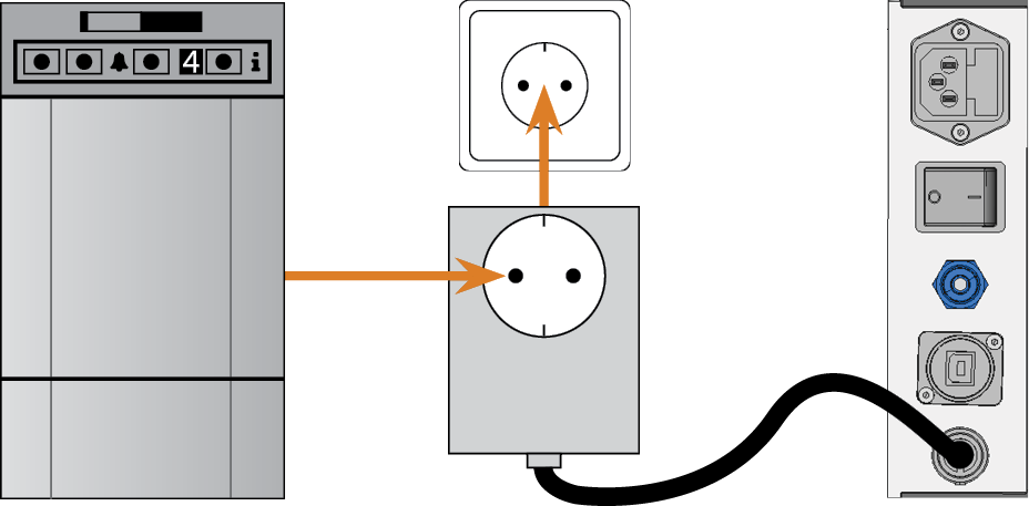
The machine requires an uninterruptible power supply for proper operation.
- Plug the provided power cable into the mains connection on the connection panel of the machine.
-
NOTICE! To avoid job interruptions, install an uninterruptible power supply (UPS), type online / VFI (IEC 62040-3, Class 1) if there are regular power failures or frequent mains voltage fluctuations.
- Insert the plug of the cable into a socket that is protected by a Residual Current Device / Ground Fault Circuit Interrupter.
Before operating the machine for the first time, you must remove the transport lock in the machine working chamber. The transport lock prevents the spindle from getting damaged during transport.
- Ensure the following:
- The machine is connected to the electrical source.
- The CAM computer
 The computer that is connected to your machine and which runs DentalCAM and DentalCNC. is not connected to the machine.
 - Switch on the machine at the main power switch.
- Open the working chamber door.
- Switch off the machine at the main power switch.
- Remove the transport lock as shown in the supplement.
Risk of injuries through leaking compressed air and lashing pneumatic hoses
Open or loose pneumatic connections can cause severe injuries.
- Ensure that during installation and maintenance of the pneumatic hoses and of the compressed air regulator compressed air is not conducted through the hoses and connections.
- Before conducting compressed air through the hoses and connectors, verify that the hoses are securely inserted into the correct connectors and that they are not damaged. This also applies to the compressed air regulator.
- Do not conduct compressed air through damaged hoses and connectors.
Bearing failure and electrical damage to the spindle in case of contaminated compressed air
The incoming compressed air must be dry and oil-free according to ISO 8573-1:2010 because the compressed air regulator only serves as an indicator for contaminated air.
| Air purity according to ISO 8573-1:2010 | ||
|---|---|---|
|
Solid particles |
class 3 |
Filtration degree better than 5 µm for solid particles |
|
Water |
class 4 |
Maximum pressure dew point: +3 °C |
|
Total oil content |
class 3 |
Maximum oil content: 1 mg/ml3 |
- Ensure that the compressed air meets the above requirements.
- Only connect the machine to the compressed air supply if the compressed air regulator is properly installed.
- Connect the machine to the compressed air supply only via the provided compressed air regulator.
You can find specific values and additional requirements in the chapter on technical data. Technical data
The machine requires the compressed air for the following tasks:
- For the opening and closing of the collet chuck during tool changes.
- For the spindle sealing air which prevents foreign bodies from entering the spindle.
- For the sealing air in the working chamber that keeps machining debris away from sensitive machine parts.
- For the ionizer.
The machine is connected to the external air supply via a compressed air regulator. You can use this regulator to monitor and regulate the pressure of the incoming air.
- 1/8” internal thread, fitted with male compressed air connector to connect the external compressed air supply
- 6 mm push-in fitting to connect the machine.
Failure of the water separator caused by a wrong alignment of the compressed air regulator.
The compressed air regulator must always be mounted in an upright position because otherwise the water separator will not work.
- Mount the compressed air regulator in an upright position.
On the left side of the machine are two bores which you can use to mount the compressed air regulator on the machine.
- Mount the compressed air regulator in an upright position, using the oval-head screws provided in the bores.
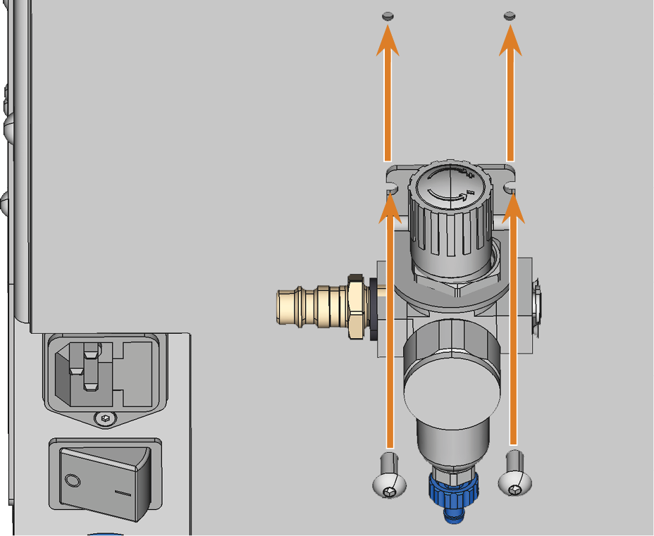
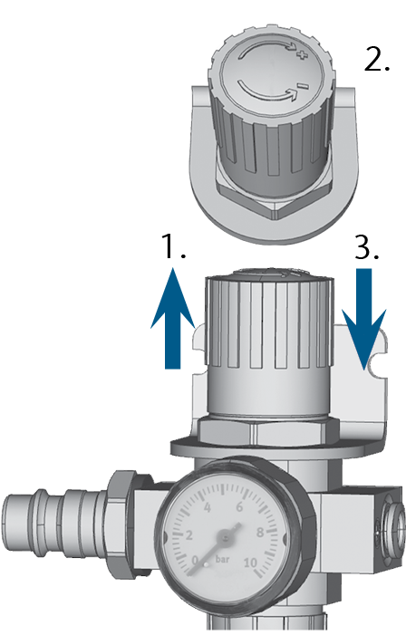
Mounting the compressed air regulator
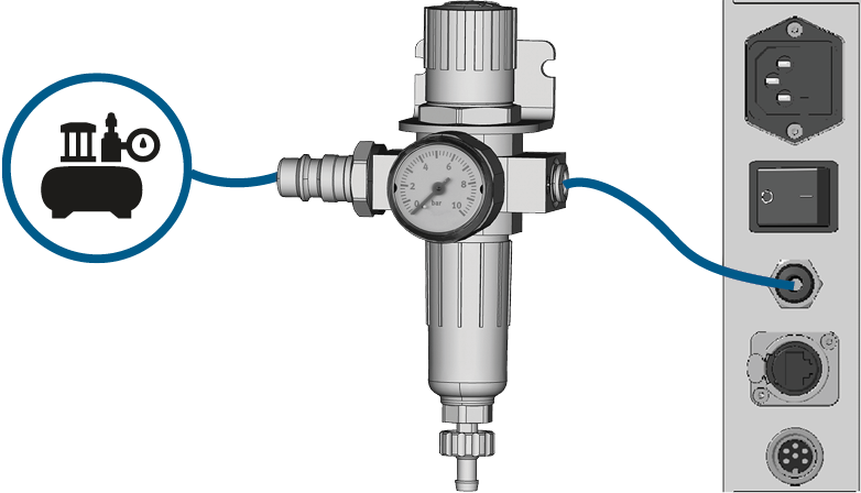
Installing the pneumatic hose
- Close the main external compressed air supply valve.
- Use the provided pneumatic hose to connect the right pneumatic connection of the compressed air regulator to the pneumatic connection of the machine.
- Connect the external compressed air supply to the left pneumatic connection of the compressed air regulator.
- Thoroughly verify that all external pneumatic hoses are properly seated in their corresponding connections and that the hoses and connectors are undamaged.
- If all hoses and connectors are properly installed and undamaged, open the external compressed air supply valve.
Setting the air pressure is only necessary if the air pressure shown by the pressure gauge does not lie between the minimum and maximum air pressure. You can find specific values and additional requirements in the chapter on technical data.
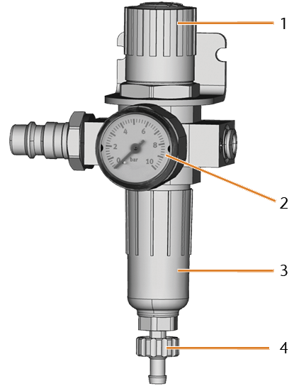
- Rotary knob for pressure regulation
- Pressure gauge for monitoring the outgoing air pressure
- Bowl of the water separator
- Discharge screw
-
Pull the rotary knob on top of the compressed air regulator slightly upwards.
- Turn the rotary knob in the desired direction:
- Turn it in the “+” direction to increase the pressure
- Turn it in the “-” direction to decrease the pressure
- Push the rotary knob down again.
- The knob is locked and cannot be changed inadvertently.
Components of the air extraction system:
| Component | Source | Required? | Prerequisite |
|---|---|---|---|
|
Suction unit incl. suction hose |
Customer service, specialist dealers |
Yes |
– |
|
Switching unit |
Customer service* |
No |
Data cable not used |
|
Data cable of supported suction units |
Manufacturer of the suction unit |
No |
Supported suction unit; switching unit not used |
|
Hose connection |
Customer service |
If the suction hose does not fit |
– |
*The switching unit is not available worldwide.
You can find specific values and additional requirements in the chapter on technical data. Technical data
- Use a suction device with the following properties only:
- Designed for the commercial use in the dental sector
- Equipped with a filter of the filter class M
- Equipped with safety devices which protect you from static discharges (e. g. through an anti-static suction hose)
You can install the suction unit as follows:
-
Read the documentation for the suction unit. Follow the operating and safety instructions at any time.
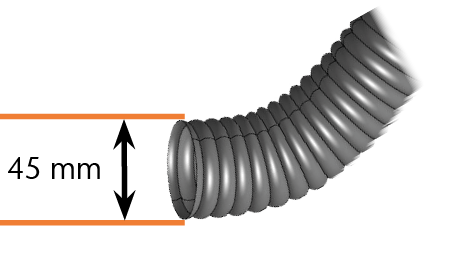
-
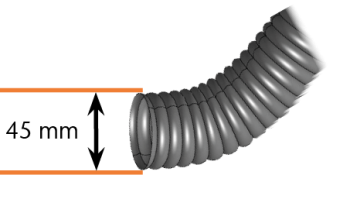
Check if the connection of the suction hose has an outer diameter of 45 mm.
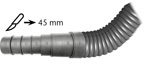
-
If the diameter is different, adjust either the hose or the hose adapter supplied with the suction unit.
Alternative: Use the optional hose connection of vhf.
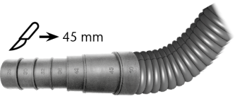
Example: Suction hose with hose adapter
or
Hose connection
-
Insert the suction hose into the opening for the suction unit on the machine. Make sure that the suction hose is properly seated.
-
Continue with the installation of the suction unit as described in the documentation of the unit.
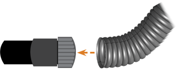
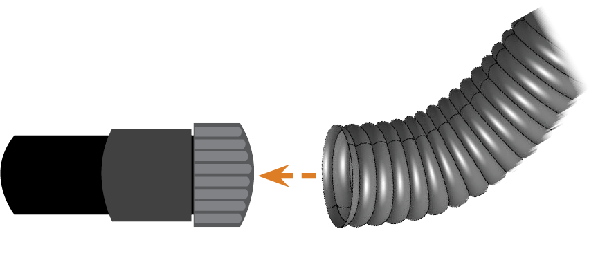
If you cannot connect the suction hose of the suction unit directly to the machine, install the hose connection as follows:
- Obtain the hose connection from customer service.
- Turn the thread of the hose connection counterclockwise until the connection is completely open.
- Insert the suction hose of the suction device completely into the hose connection on the side of the thread.
- Turn the thread of the hose connection clockwise as far as you can.
- Insert the hose connection into the opening for the air extraction system of the machine. Ensure it is firmly connected.
If the thread gets detached from the hose connection, place it onto the connection again and turn it clockwise once so that it is screwed to the connection again.
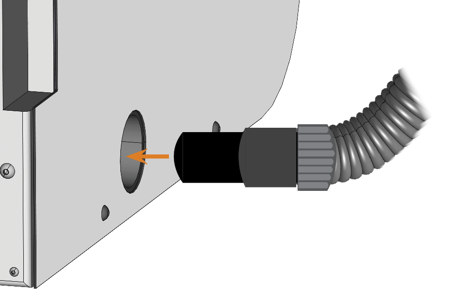
Inserting the hose connection into the opening for the air extraction system
If you want the machine to automatically switch the suction unit on and off, but a data cable is not available, you can use the optional switching unit. The switching unit is not available worldwide.
- Connect the power cable of the suction unit to the switching unit.
- Connect the control cable of the switching unit to the air extraction interface at the connection panel of the machine.
- Plug the switching unit into a power socket.
Connecting the switching unit to the suction device and the machine
The following diagram visualizes how commands are sent to the machine with our network technology:
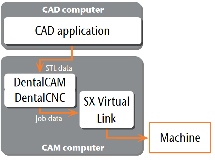
SX Virtual Link is similar to a device driver that transfers data between DentalCNC and the machine.
The network integration workflow is as follows:
- Preparing the installation
- Configure SX Virtual Link and DentalCNC.
For integrating the machine into your network, you will require the assistance of your IT specialist.
-
Ensure that your network is working without disruptions. Network failures will lead to aborted jobs and unusable machining results.
-
Do not contact customer support for setting up your network or troubleshooting network issues. Customer service will only help you with machine-related issues.
- If you want to control multiple machines with 1 CAM computer The computer that is connected to your machine and which runs DentalCAM and DentalCNC., use our multi-machine control feature. See the documentation for the manufacturing software.
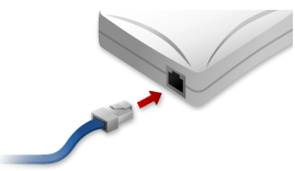
- Plug the Ethernet cable into the network port at the connection panel of the machine.
- Plug the other end of the Ethernet cable into the network port of the CAM computer The computer that is connected to your machine and which runs DentalCAM and DentalCNC.. Do not use a router, hub or switch to connect the 2 units at this point.
- Make sure that you have administrator rights on the CAM computer The computer that is connected to your machine and which runs DentalCAM and DentalCNC..
-
Install DentalCAM & DentalCNC. Installing DentalCAM & DentalCNC
-
During installation, the SX Virtual Link setup program
A separate program called "Setup.exe" which installs the applications on your hard drive. opens.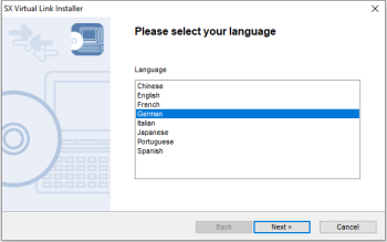
-
If the SX Virtual Link setup program
A separate program called "Setup.exe" which installs the applications on your hard drive. opened, continue with the next step.If the SX Virtual Link setup program
A separate program called "Setup.exe" which installs the applications on your hard drive. did not open, open the installation program in the DentalCAM & DentalCNC installation folder The folder on your hard drive that you installed DentalCAM and DentalCNC in..USB\Silex\Cosetup.exe
-
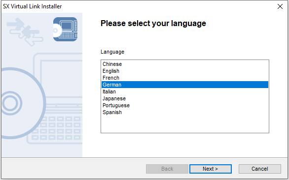
Follow the SX Virtual Link setup program
A separate program called "Setup.exe" which installs the applications on your hard drive. until the installation is finished. -
Continue with the DentalCAM & DentalCNC installation.
Watch the video

YouTube video – When viewing this video, personal data is sent to YouTube, LLC, USA. Privacy statement
-
Ensure that the CAM computer
The computer that is connected to your machine and which runs DentalCAM and DentalCNC. is directly connected to the machine via an Ethernet cable. Otherwise, the machine may obtain incorrect network settings and may become unreachable.If this happens, an on-site visit by customer service may be necessary: What to do if the machine is unreachable
- Switch on the machine at the main power switch.
-
The working chamber is illuminated in white.
The machine does not reference.
- Open the SX Virtual Link application window:
-
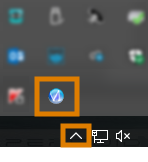
The software should already be running – select the arrow on the right side of your task bar to open the system tray.
In the system tray, select the SX Virtual Link icon.
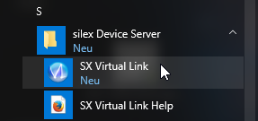
- If the SX Virtual Link icon is not in the system tray, start the application via the start menu. You should find it in the Silex Device Server group.
-
The SX Virtual Link application window displays.
-
If SX Virtual Link cannot find your machine, the following image displays in the window:
-
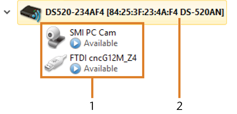
If SX Virtual Link has found your machine, the internal network devices of the machine display in the window.
-
If the machine was found, continue with the next step.
If the machine was not found, do the following:
-
Check if the CAM computer
The computer that is connected to your machine and which runs DentalCAM and DentalCNC. is properly connected to the machine. -
Restart the machine.
-
 In the SX Virtual Link application window, select the depicted icon.
-
A more detailed list of the network devices displays.
- The internal devices of the machine
- The superior list entry for the machine
- In the SX Virtual Link window, right-click on SMI USB 2.0 Camera.
- From the context menu, select Properties….
- Switch to the Disconnect tab.
- Activate the Allow auto-disconnect when a Request Use is received check box.
- From the Auto-disconnect timeout drop-down list, select 10.
- To save your settings, select OK.
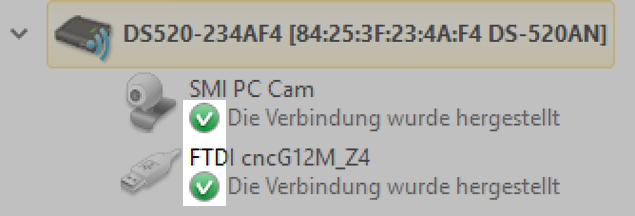
- Right-click on SMI PC Cam.
- From the context menu, select Connect.
- In the SX Virtual Link window, locate the device whose name starts with FTDI. Repeat steps 7 – 13 for this device.
- Green check marks (marked orange) indicate that the connections have been established.
 In the SX Virtual Link application window, select the depicted icon.
- The Options window opens.
- In the Options window, activate the following options:
- Launch SX Virtual Link at Windows startup
- Don't show SX Virtual Link main window on program launch
- Hide the main window if the close button is clicked
-
Deactivate the Automatically connect newly discovered USB devices option.
- To save your settings, select OK.
-
Start DentalCNC.
-
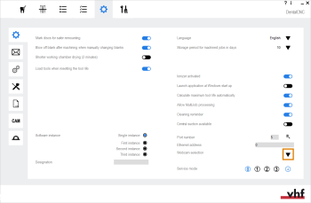
Open the DentalCNC Application settings with the following icon in the main icon bar:

-
Open the General settings with the following icon in the local icon bar:

-
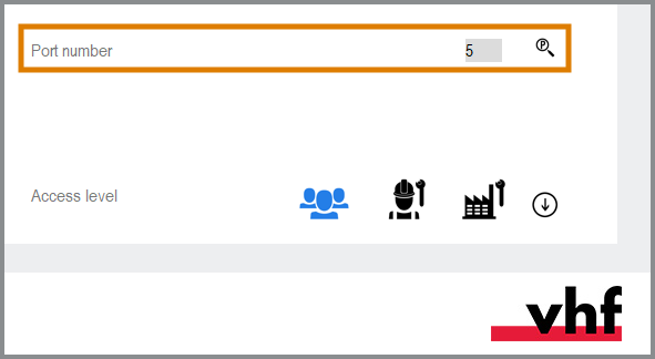
Select the following icon next to the Port number input field:

-
If DentalCNC is able to determine the port number, the number displays in the Port number input field. The machine references.
-
Read out the Ethernet address (marked orange) in the application window of SX Virtual Link. It displays behind the device name.

- Enter the Ethernet address into the Machine Ethernet address input field in DentalCNC.
Example:84:25:3F:23:4A:F4
- Press Enter.
- From now on, DentalCNC will connect and disconnect the machine.
- Activate the option Launch application at Windows startup in DentalCNC.
- From now on, DentalCNC will launch with Windows®. This is required to automate the connection process.
-
Quit DentalCNC.
If you do not close DentalCNC now, your changes may not be saved.
- In the SX Virtual Link application window, right-click on SMI USB 2.0 Camera.
- From the context menu, select Disconnect.
- Right click on the entry starting with FTDI.
- From the context menu, select Disconnect.
- In the SX Virtual Link application window, the 2 check marks no longer display.
- Start DentalCNC.
- DentalCNC establishes the connection to the machine. The 2 check marks display again.
-
(Optional) Install hub, router or switch to connect the computer and the machine. This may require additional configuration.
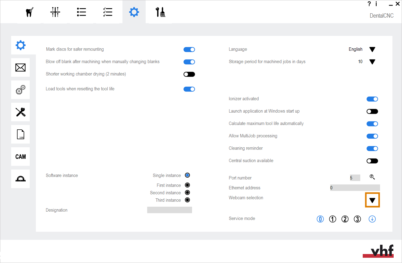
In the following cases, you need to configure the webcam of the machine:
- First installation of the machine
- Exchange of the CAM computer The computer that is connected to your machine and which runs DentalCAM and DentalCNC.
- Exchange of the control unit
- Exchange of the webcam
- Open the DentalCNC Application settings with the following icon in the main icon bar:
-
Open the General settings with the following icon in the local icon bar:
-
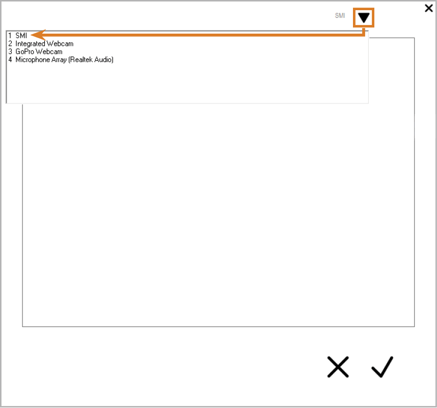
Select the following icon next to the Webcam selection label:

- Select the webcam SMI from the drop-down list at the top of the window.
-
The current still image of the webcam displays.
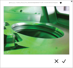
- Select the depicted icon:

- The window closes. The webcam configuration is saved to the CAM computer The computer that is connected to your machine and which runs DentalCAM and DentalCNC..

While the network connection to your machine should work automatically, there are some useful things that you or your IT specialist should know.
What to do when devices are in use in SX Virtual Link
If SX Virtual Link displays that 1 or more devices are in use, another computer running SX Virtual Link has taken control of them.
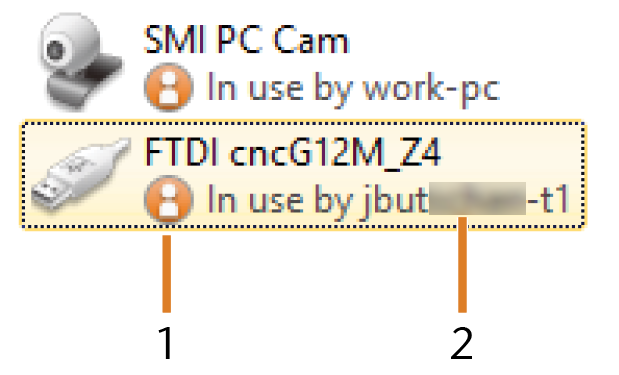
Devices that are in use by other computers
- “In use” icon
- Name of the computer that is using the device
You can send a use request to the computer that is currently connected to the device. If the request is accepted, your computer can connect to the device.
- In the SX Virtual Link application window, right-click on the corresponding device.
- From the context menu, select Use request.
- The request displays in a pop up window on the receiving computer. If the request is accepted, your computer will connect to the device after a short amount of time.
What to do if the machine is unreachable
If the network settings that are saved in the machine are incorrect, your IT specialist may try the following to connect to the machine:
- Access the router to which the machine is connected.
- Determine the IP address of the machine via the router’s configuration menu.
- Configure the machine’s network settings via the web server (see below).
- If this is not possible, ask customer service to reset the machine’s network settings through hardware access.
Network configuration via the machine's web server
The machine features a web server which allows for network configuration and network diagnostics.
You can access the web server as follows:
- Make sure that SX Virtual Link is connected to your machine.
- In the SX Virtual Link application window, right-click on the entry for the desired machine. If necessary, use the Ethernet address (marked orange) to identify the machine.
- From the context menu, select Display the Web Page.
- The default web browser launches and automatically connects to the machine's web server. You are prompted to enter a password.
- Enter the password and press Enter. If you have never set your own password, just press Enter.
- The start page of the web server displays.

Resetting the network configuration to factory defaults
In case of network problems, you can try resetting the machine's network configuration to default settings.
After the reset, you will have to reconfigure the machine's network settings.
- If you still have access to the machine's web server, do as follows:
- Log in to the web server.
- In the left column, select Settings Initialization from the Maintenance section.
- Select Yes twice.
- Wait 30 seconds.
- Restart the machine.
- If you do not have access to the web server, contact customer service.