Exchanging the spindle unit
Recommendation: If you want to exchange the spindle and the bellow at the same time, we recommend the following order:
-
Detach the bellow from the spindle unit.
-
Remove the spindle unit.
-
Remove the bellow.
-
Install the spare bellow and attach the spare bellow frame.
-
Install the spare spindle unit.
-
Attach the spare bellow in the working chamber.
Description steps 1, 3, 4, 6: Exchanging the bellow
Description steps 2, 5:
Watch the video
YouTube video – When viewing this video, personal data is sent to YouTube, LLC, USA. Privacy statement
When exchanging the spindle, exchange the entire spindle unit, which consists of the following components:
-
Spindle including collet chuck
-
Collet chuck release unit including cable
The spindle unit is located behind the top service cover and the safety cover:
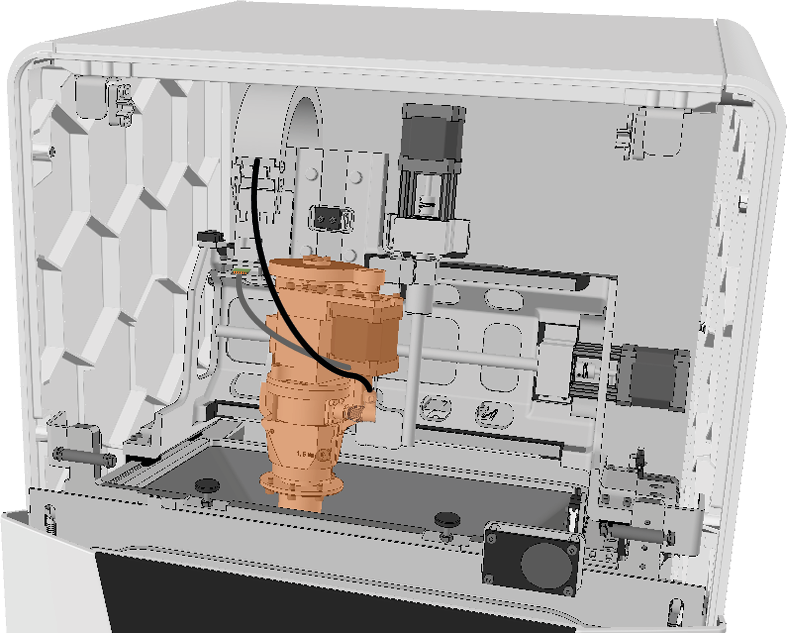
Spindle unit in the machine interior (marked orange)
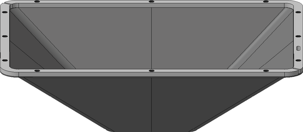
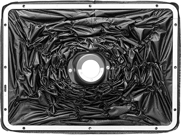
Some steps depend on the version of bellow installed. There are 2 versions that differ visually:
-
Variant A:
-
Variant B:
-
Have ready:
-
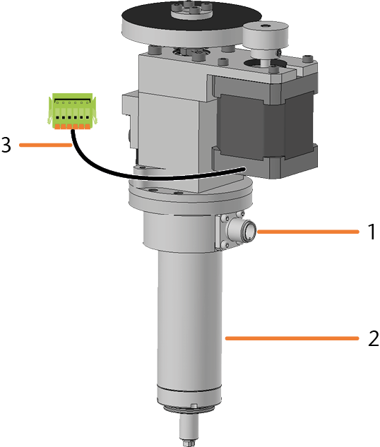
1 x Spare spindle SFE 300E
-
Connection for the spindle cable
-
Spindle including collet chuck
-
Cable of the collet chuck release unit with plug
-
-
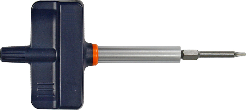
1 x Torque screwdriver 1.5 Nm with TX20 bit
-
-
Start dentalcnc.
-
Open the Service Assistant with the following icon in the Main icon bar:

-
For the Exchange spindle task, select the Start button.
-
The spindle moves into the spindle exchange position.
-
Open the working chamber door.
-
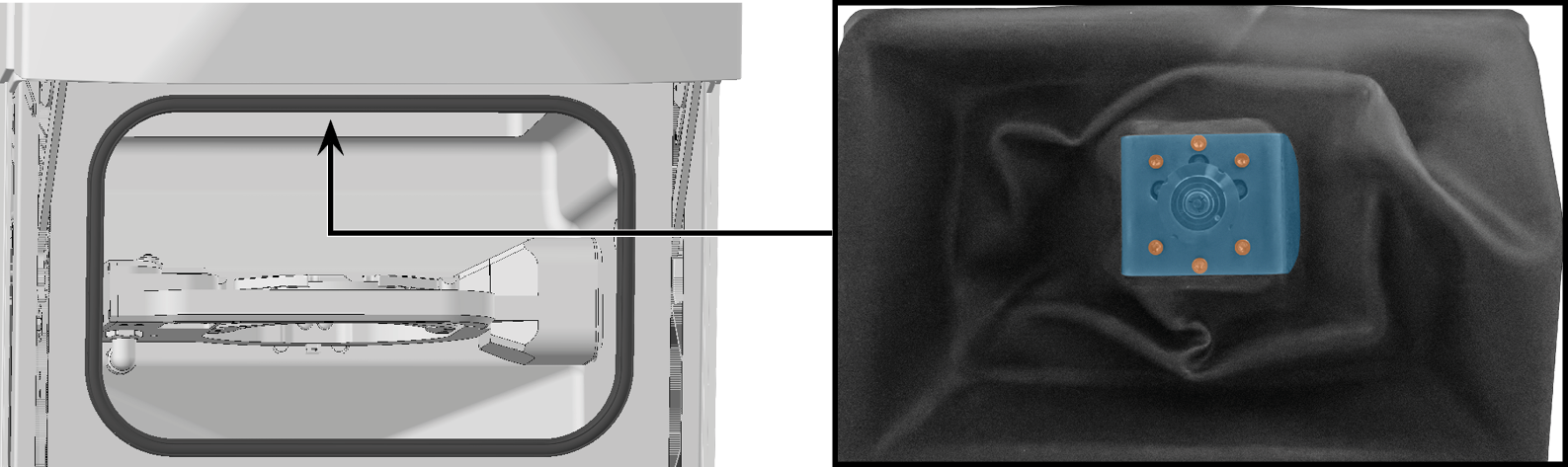
If bellow variant A is installed:
-
Loosen the 6 screws of the bellow fixation plate using the torque screwdriver.
-
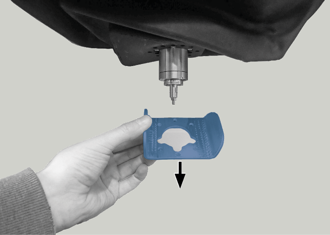
Pull the bellow fixation plate downwards from the bellow. When exchanging for bellow variant B, you no longer need the bellow fixation plate.
-
-
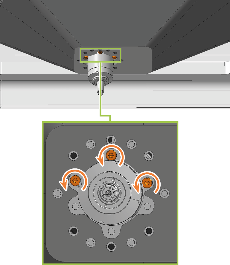
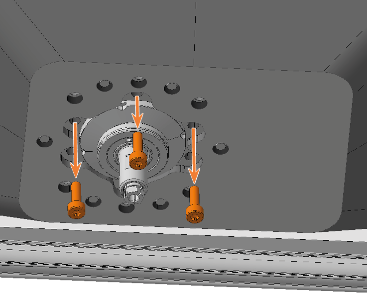
Use the TX10 angle screwdriver to loosen the 3 screws that secure the bellow to the spindle unit.
-
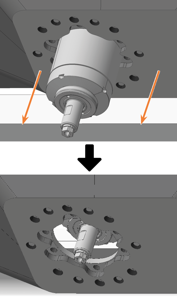
Pull the bellow as far down as possible over the spindle.
-
Close the working chamber door.
-
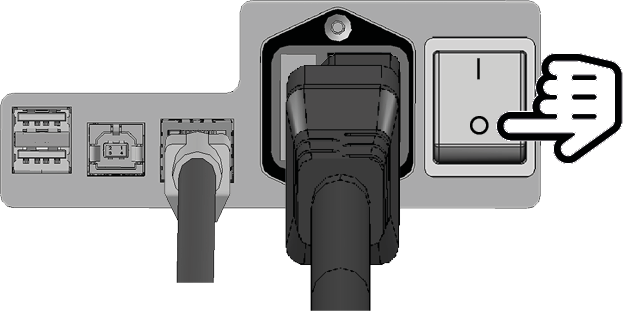
Switch off the machine at the main power switch.
-
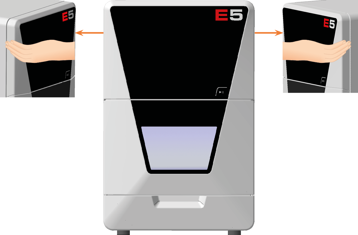
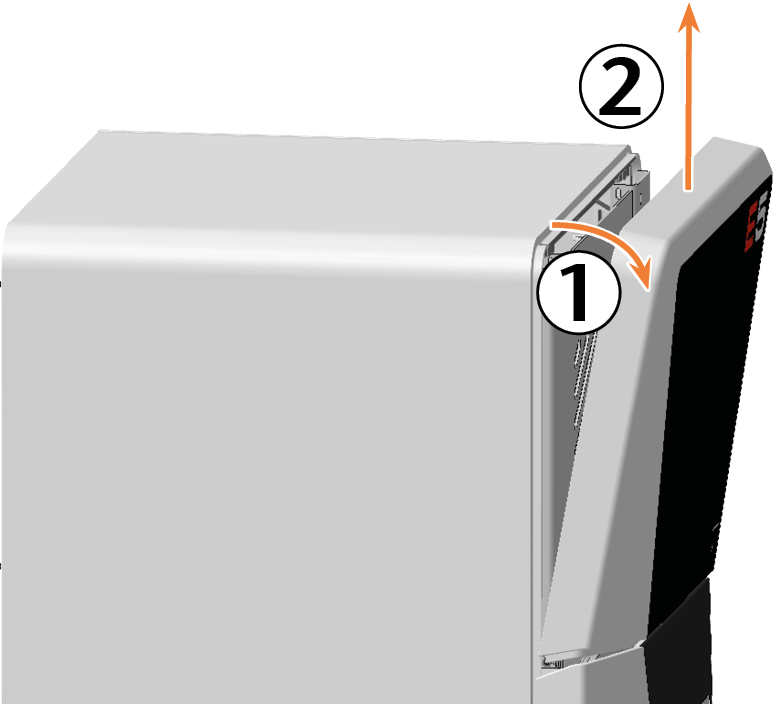
Remove the top service cover:
-
Grasp the recess on the left and right sides of the service cover.
-
Lift the service cover out of the tabs.
-
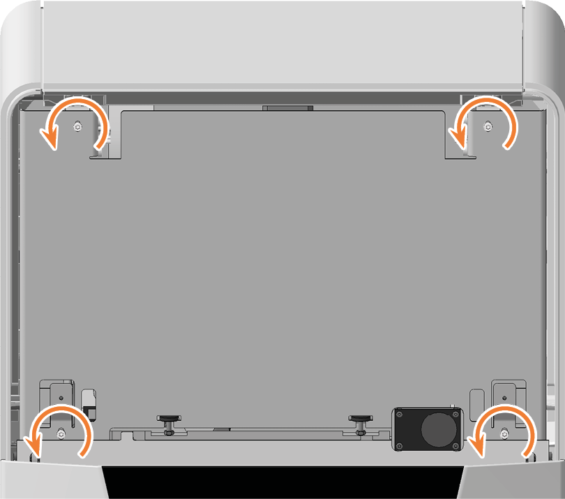
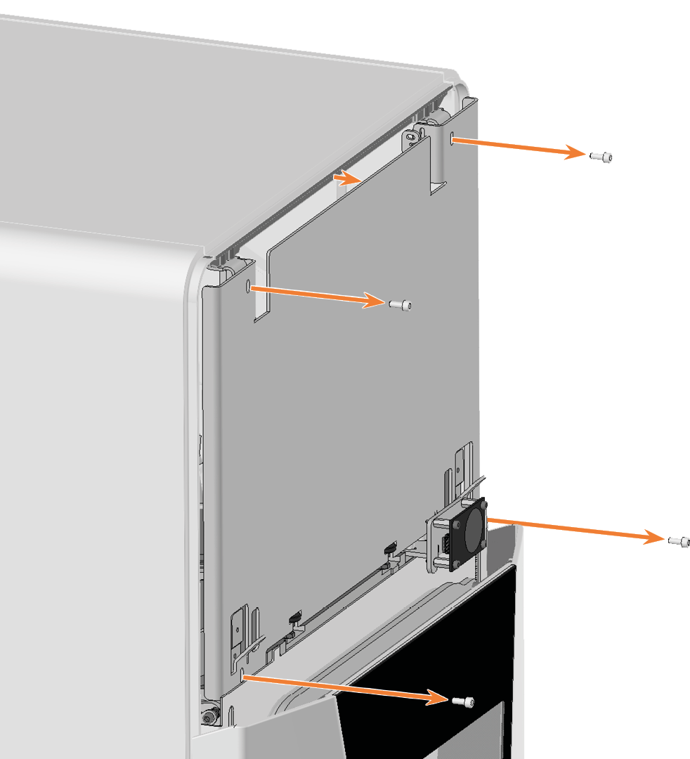
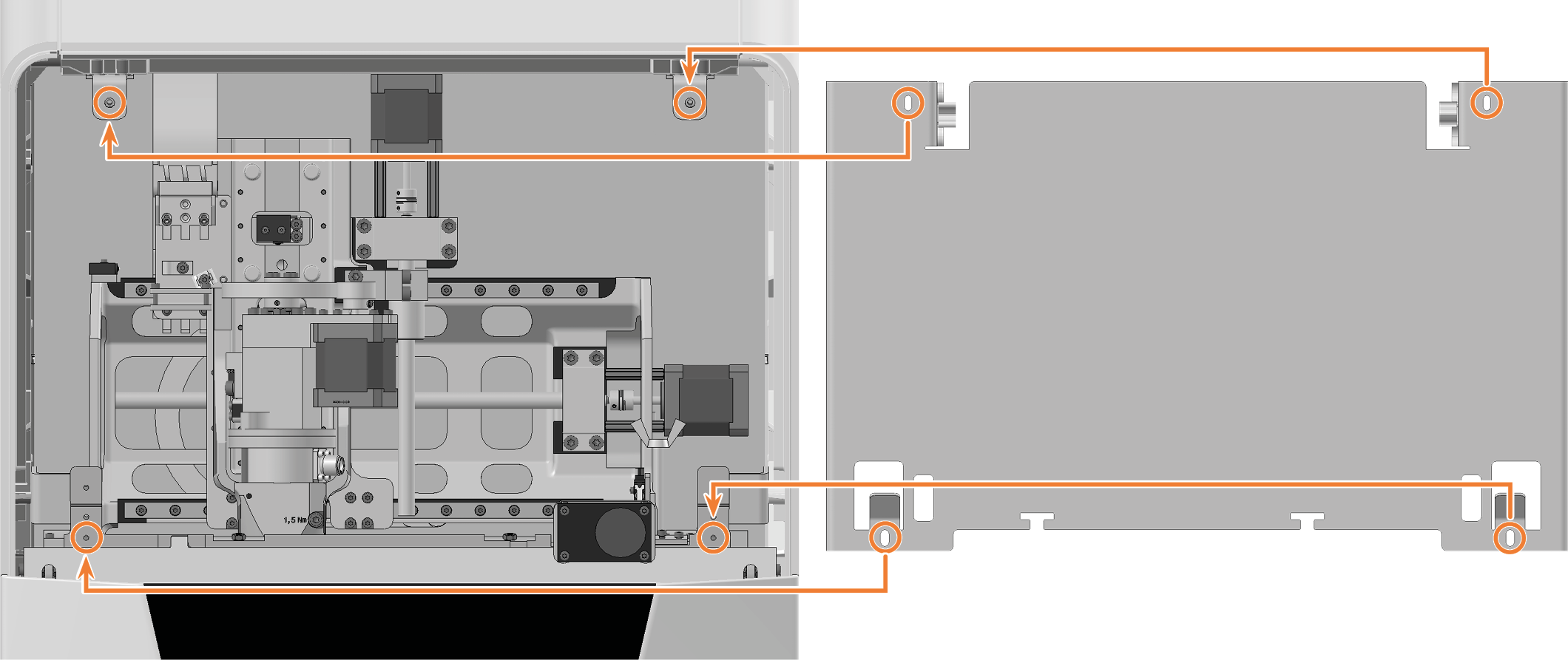
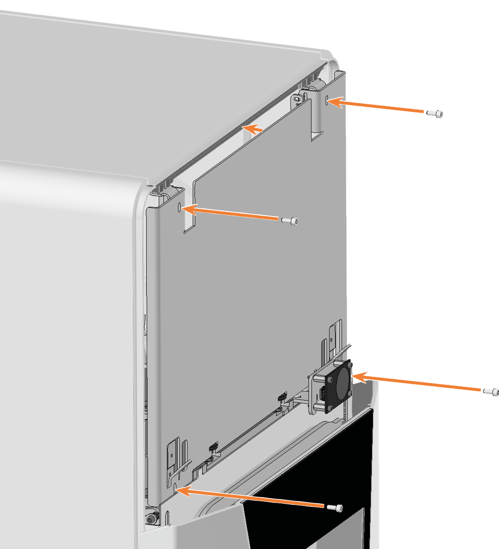
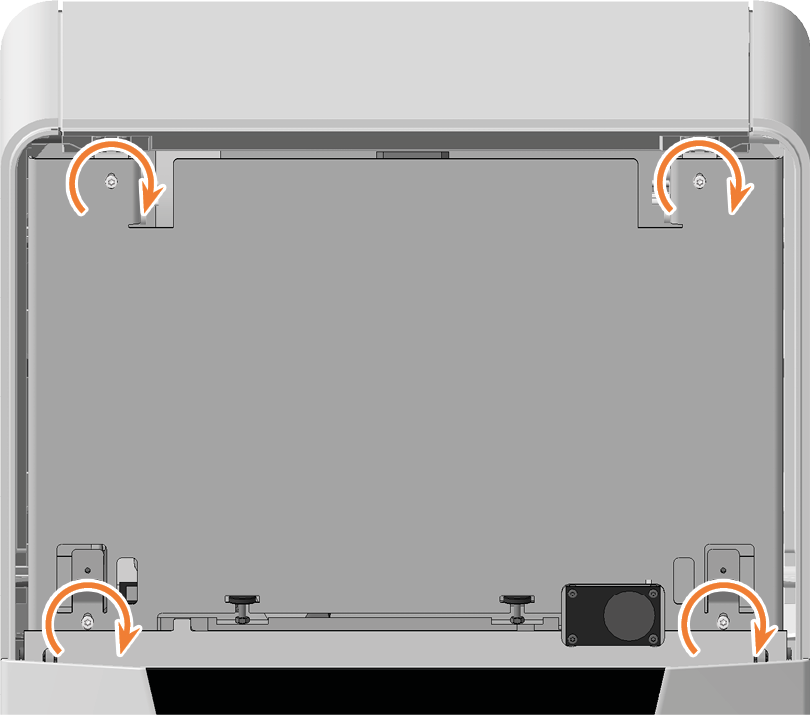
Use the 1.5 Nm torque screwdriver to unscrew the 4 screws that secure the safety cover.
-
Remove the safety cover.
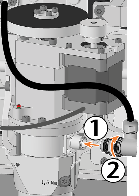
- Loosen the spindle cable by turning the knurled nut toward you.
-
Unplug the spindle cable from the spindle connector.
-
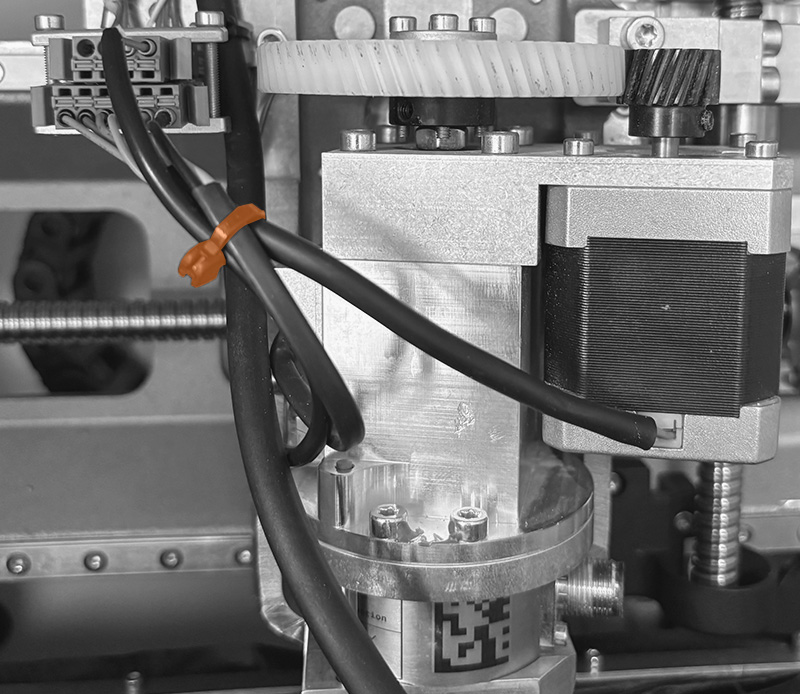
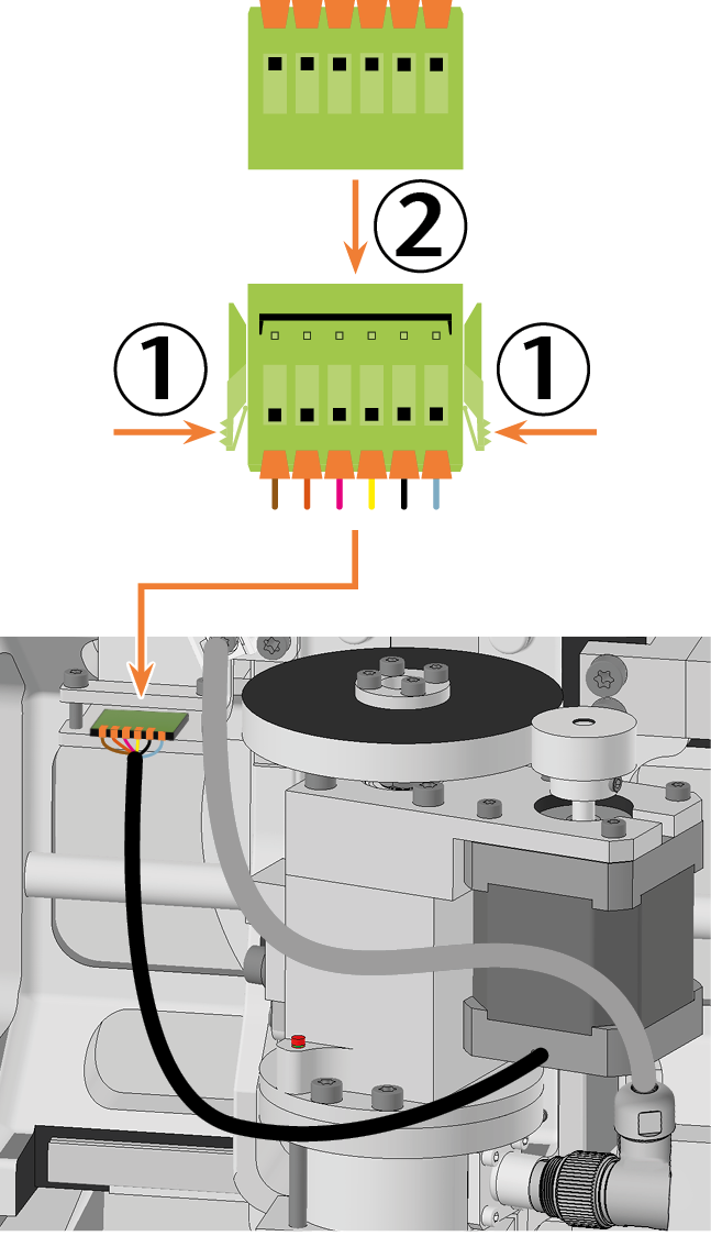
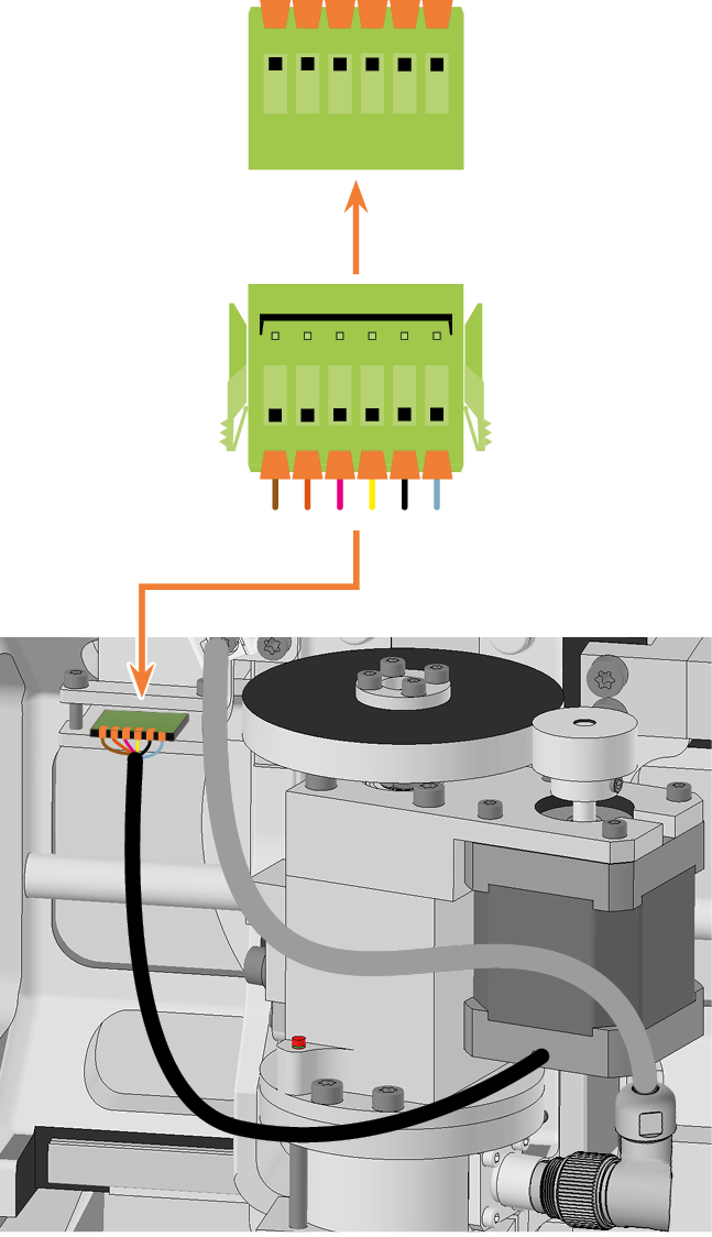
2 cables with 1 single shared connector extend from the collet chuck release unit.
Cut the cable tie that connects the 2 cables from the collet chuck release unit to the temperature sensor cable.
-
Unplug the cable from the collet chuck release unit:
Push both mounting clips on the connector toward the center and pull the connector out of the socket.
-
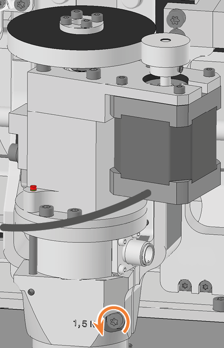
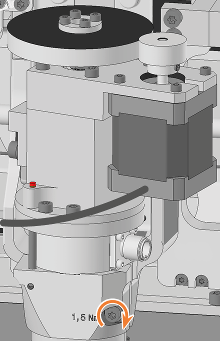
Loosen the fixing screw with the torque screwdriver. Do not unscrew the screw completely.
-
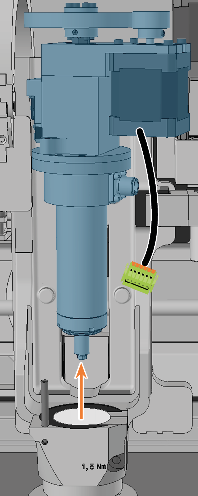
Remove the spindle by pulling it upward out of the spindle holder.
-
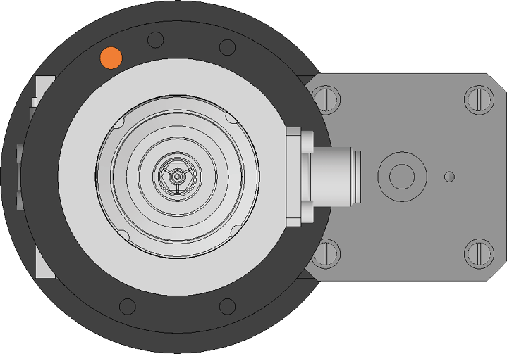
Pick up the spare spindle and locate the positioning pin hole (marked orange) on the bottom.
-
Rotate the spindle so that the positioning pin aperture (marked orange) is in the front left.
-
Insert the replacement spindle from above into the spindle holder:
-
Insert the positioning pin on the spindle bracket (marked in green) into the positioning pin opening (marked in orange) in the spindle.
-
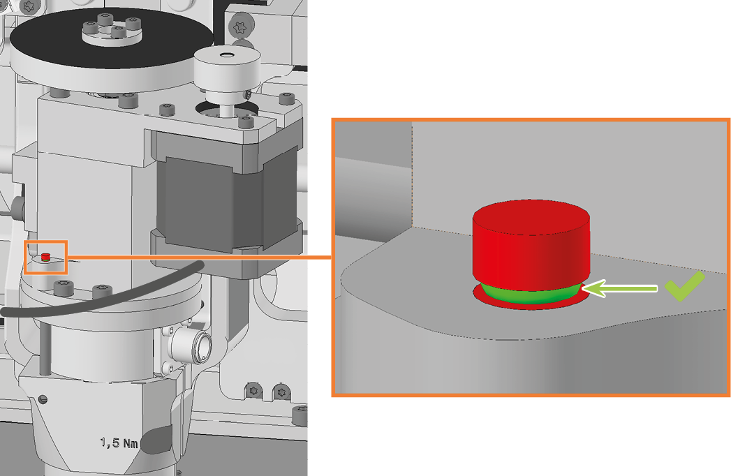
Gently push the spindle down, paying attention to the spindle height indicator.
-
-
Once you have pushed the spindle down sufficiently, you will see the green ring on the spindle height indicator.
-
Tighten the screw to fix the spindle using the torque screwdriver.
-
Plug the spindle cable into the spindle connector.
-
Tighten the spindle cable by manually turning the knurled nut away from you.
-
Insert the collet chuck release unit cable into the corresponding connector in the machine.
-
Use a cable tie to tie the 2 cables from the collet chuck release unit together with the temperature sensor cable.
-
Position the safety cover so that the 4 screw holes are located above the 4 screw holes in the machine housing.
-
Secure the safety cover to the machine housing using the 1.5 Nm torque screwdriver.
-
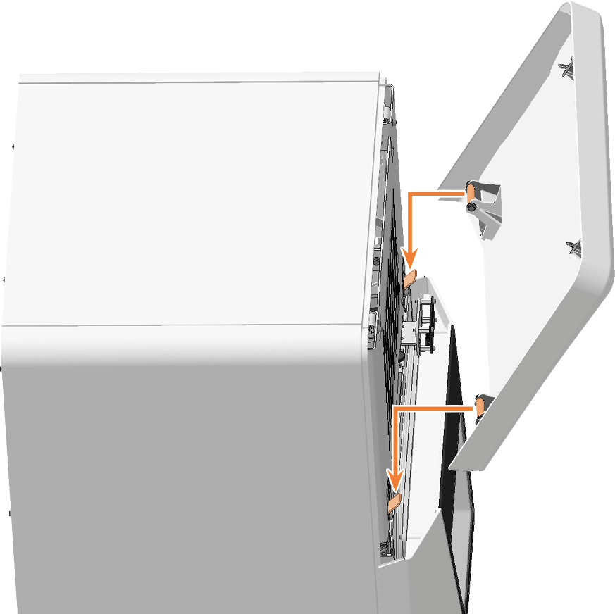
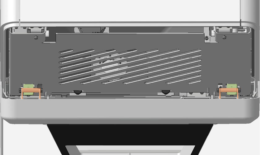
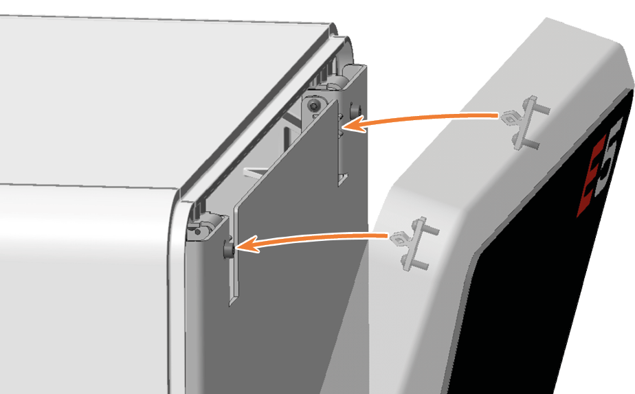
Attach the top service cover:
-
Insert the bolts (marked orange) of the service cover into the holders (marked green) on the safety cover.
-
Tilt the service cover towards the machine until it clicks into place.
-
-
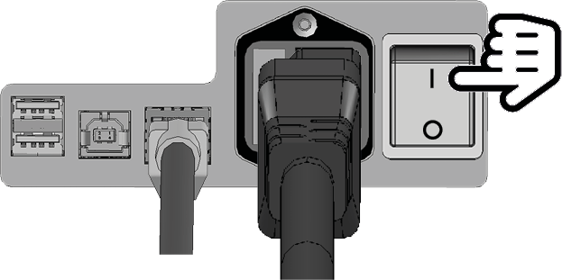
Switch on the machine at the main power switch.
-
Open the working chamber door.
-
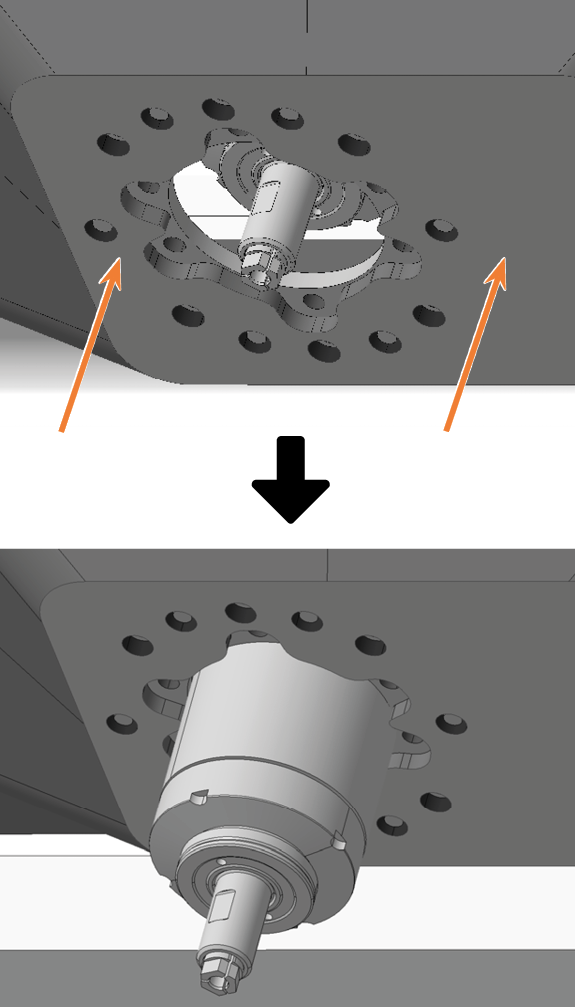
Pull the opening of the bellow upwards over the spindle until it reaches the stop and hold the bellow in this position.
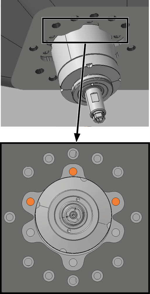
The holes for the screws used to secure the bellow must be located over the corresponding screw holes in the spindle unit.
-
Use the TX10 angle screwdriver to tighten the bellow with 3 screws in the front screw holes:
-
Carefully place the first screw and check if you can screw it in. If this is not possible, correct the position of the bellow.
-
Screw in all screws first without tightening them. This allows you to correct the position of the bellow.
-
Once you have screwed in all the screws properly, tighten them.
-
-
Version A of the bellow:
-
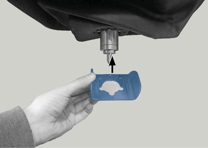
Align the bellow fixation plate as shown in the following figure.
-
Slide the bellow fixation plate over the spindle up to the bellow.
The holes for the 6 screws of the bellow fixation plate must be located over the corresponding screw holes in the bellow.
-
Use the torque screwdriver to tighten the bellow fixation plate with 6 screws:
Carefully place the first screw and check if you can screw it in. If this is not possible, correct the position of the bellow fixation plate.
-
Screw in all screws first without tightening them. This allows you to correct the position of the bellow fixation plate.
-
Once you have screwed in all the screws properly, tighten them.
-
-
Open the Service Assistant with the following icon in the Main icon bar:
-
Confirm the Exchange spindle and Exchange spindle collet chuck tasks with the Mark as complete button.
-
Mill a test specimen and calibrate the machine as necessary.
-
Contact customer service and have the spindle operating hours reset.
This can be important for deciding warranty claims.

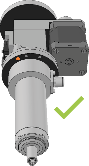
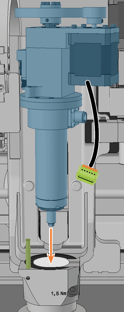
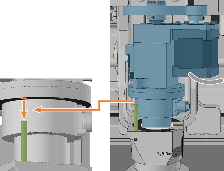
Spindle shown in higher position for clarity


