Machine overview
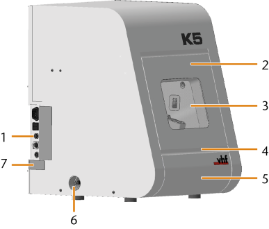
Front side of the machine
- Connection panel
- Working chamber door
- View window to the working chamber
- Recessed grip for opening the working chamber door
- Accessories container
- Hose connection for the air extraction system
- Identification plate
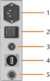
Connection panel
- Power connection including glass fuse T6,3A L250V
- Main power switch
- Pneumatic connection (6 mm push-in fitting)
- USB port
- Air extraction interface (6 pins, IEC 61076-2-106)
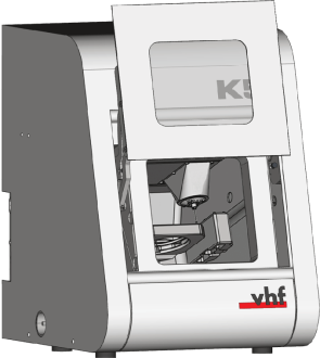
Working chamber door
The working chamber door locks the working chamber and protects the user from injuries during operation.
You cannot open the door when the machine is switched off or while the axes are moving.
- To open or close the working chamber door, pull it upwards or push it downwards with your hand. Use the recessed grip of the door.
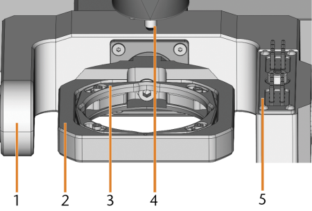
Working chamber
You can insert blanks and tools into the working chamber. This is where the blanks are machined.
- Rotational axis B
- Blank holder; Rotational axis A
- Fixing ring
- Spindle with collet chuck for picking up tools
- Tool magazine
Colors of the working chamber lighting
|
Color |
Status |
Working chamber door |
|---|---|---|
|
Green |
The machine is ready for operation. |
unlocked |
|
White |
The machine is ready for operation. |
unlocked |
|
Blue |
|
locked |
|
Red |
A machine malfunction has occured. |
locked |
Accessories container
In the accessories container below the working chamber, you can store blanks, tools and the spindle service set so they are easily accessible.
CAM computer
To operate the machine, you must use a computer running Windows® (“CAM computer![]() The computer that is connected to your machine and which runs dentalcam and dentalcnc.”) and specially designed software (“manufacturing software
The computer that is connected to your machine and which runs dentalcam and dentalcnc.”) and specially designed software (“manufacturing software![]() Term for the software package consisting of dentalcam and dentalcnc.”). The manufacturing software
Term for the software package consisting of dentalcam and dentalcnc.”). The manufacturing software![]() Term for the software package consisting of dentalcam and dentalcnc. consists of the following components:
Term for the software package consisting of dentalcam and dentalcnc. consists of the following components:
- dentalcamA CAM application for creating and calculating virtual blanks (“jobs”)
- dentalcncA CNC application for machining jobs and for maintaining the machine.
To create and design the dental objects you also need a CAD application (sold separately by specialist dealers).
Identification plate and serial number
The identification plate of the machine contains identifying information such as the serial number. You can find the identification plate and machine serial number at the following location: Front side of the machine
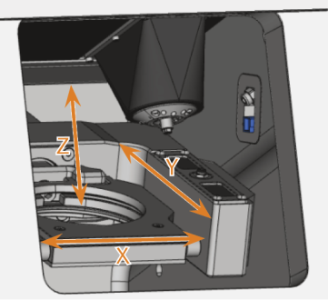
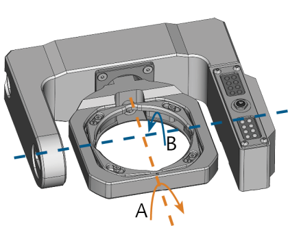
Axes
This machine has
Linear axes
The spindle moves along these axes.
Rotational axes
The blank holder rotates about these axes.
